This is the conclusion of a story that we began in the Dec. 14 issue of RWEE about designing, building and installing our own diplexer, an ultimate DIY project.
We described what led up to the project and how we settled on a new shared site. This time we’ll dig into the actual construction part of the project, from demo at the old site to final turn-on at the new.
Cris told the crew that the best battle plan goes out the window after the first shot is fired. That was certainly the case with this project.
On the very morning we were to begin, CBC-Denver engineer Keith Peterson became ill and had to be hospitalized. He and his son Seth had planned to be on hand to help, but that didn’t happen with Keith laid up. Thankfully he recovered after several days, but not until after the bulk of the project was done.
Amanda, Cris and Stephen Poole pressed on without the rest of the crew, pulling the cabinets from Ruby Hill, transporting them to KLZ, stripping them of components and power washing away 23 years of grime. Amanda really put effort into this, and the result was like-new cabinets ready for transformation.
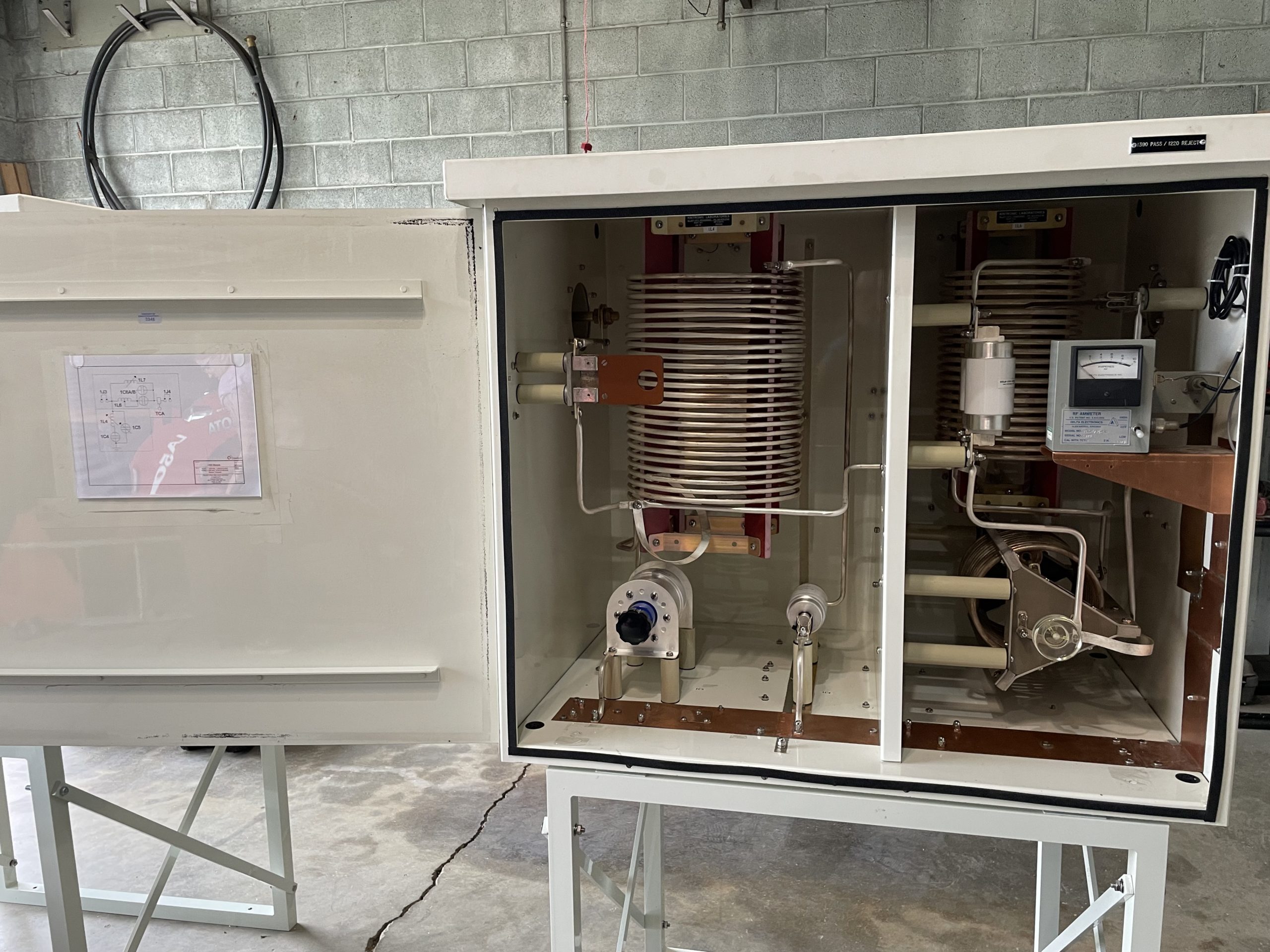
The next morning, we launched into solving the component placement puzzle, starting with the big 92 uH coils and working everything else around that, keeping all the coils mounted perpendicular to adjacent coils to minimize mutual coupling. A divider panel was included in each cabinet between the input and output sections for isolation.
We ran out of plated tubing on Tuesday. We had about a third of what we needed. The issue was that while Kintronics sells plated tubing by the pound, we use it by the foot. Somewhere in the process we wound up really short, and an additional supply had to be ordered and overnighted in.
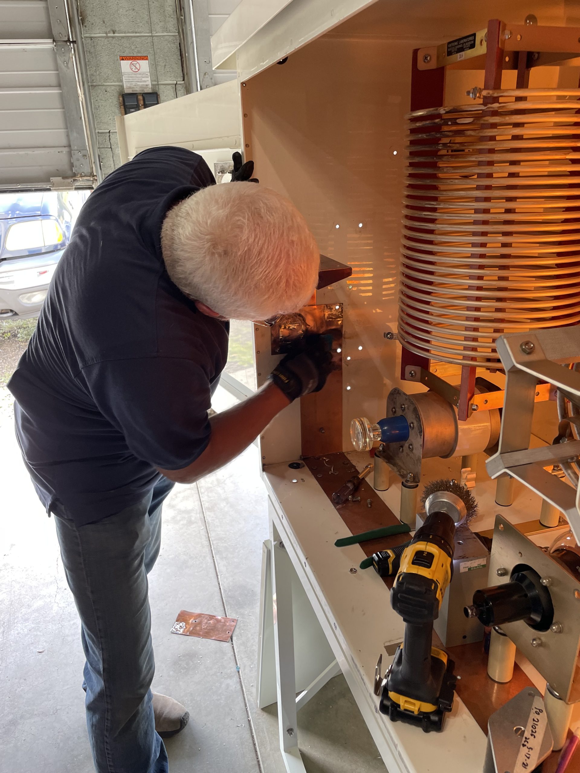
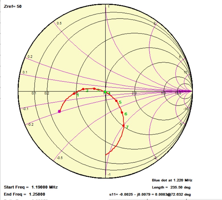
It wasn’t until the end of the day on Wednesday, after two days of drilling, tapping, measuring, bending, punching and wrenching, that the three cabinets were ready to go. We pre-tuned them at the KLZ site using a vector network analyzer initially and a signal generator and FIM as the final off-site adjustment (adjusting for minimum reject frequency current in each module).
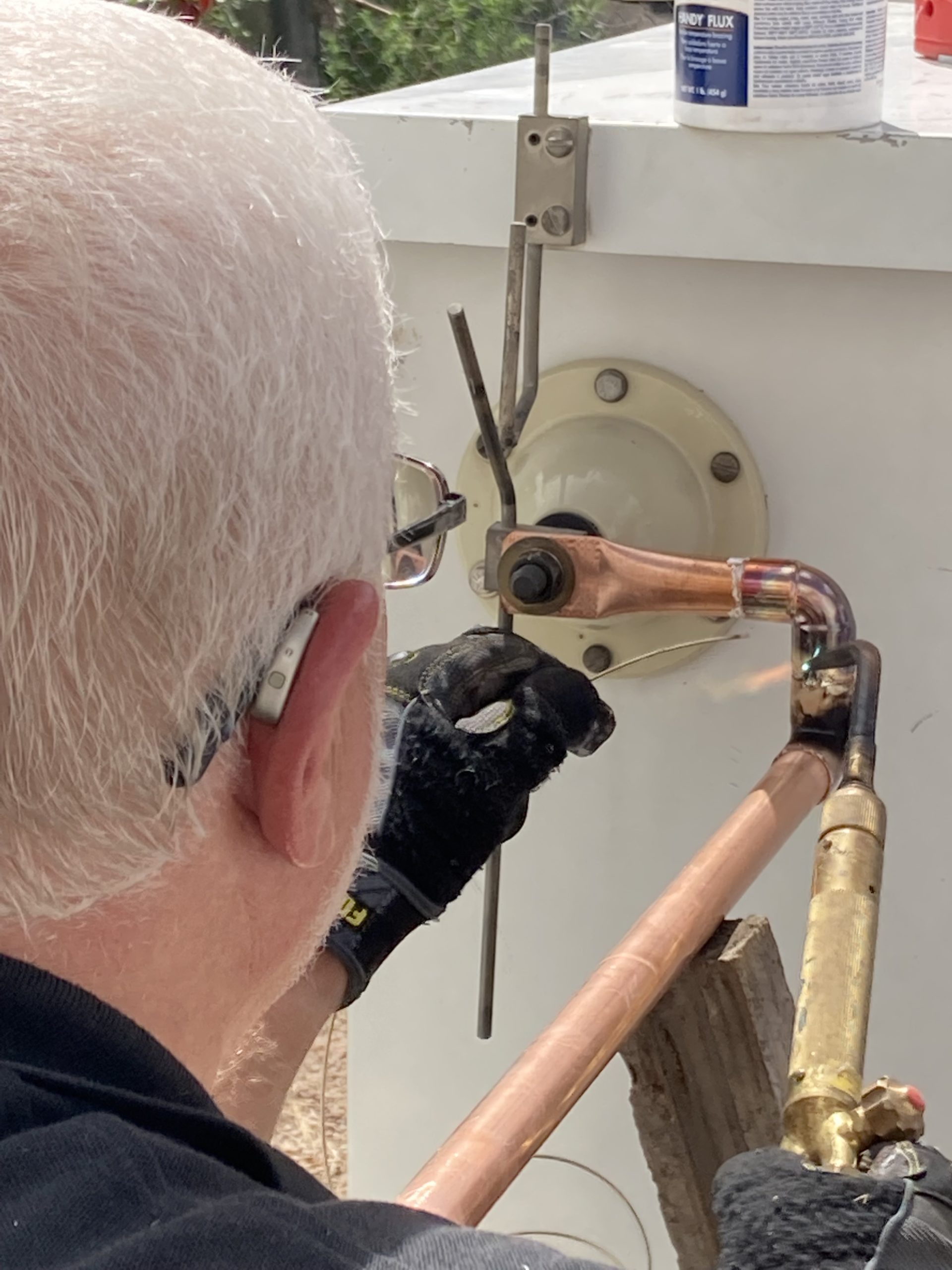
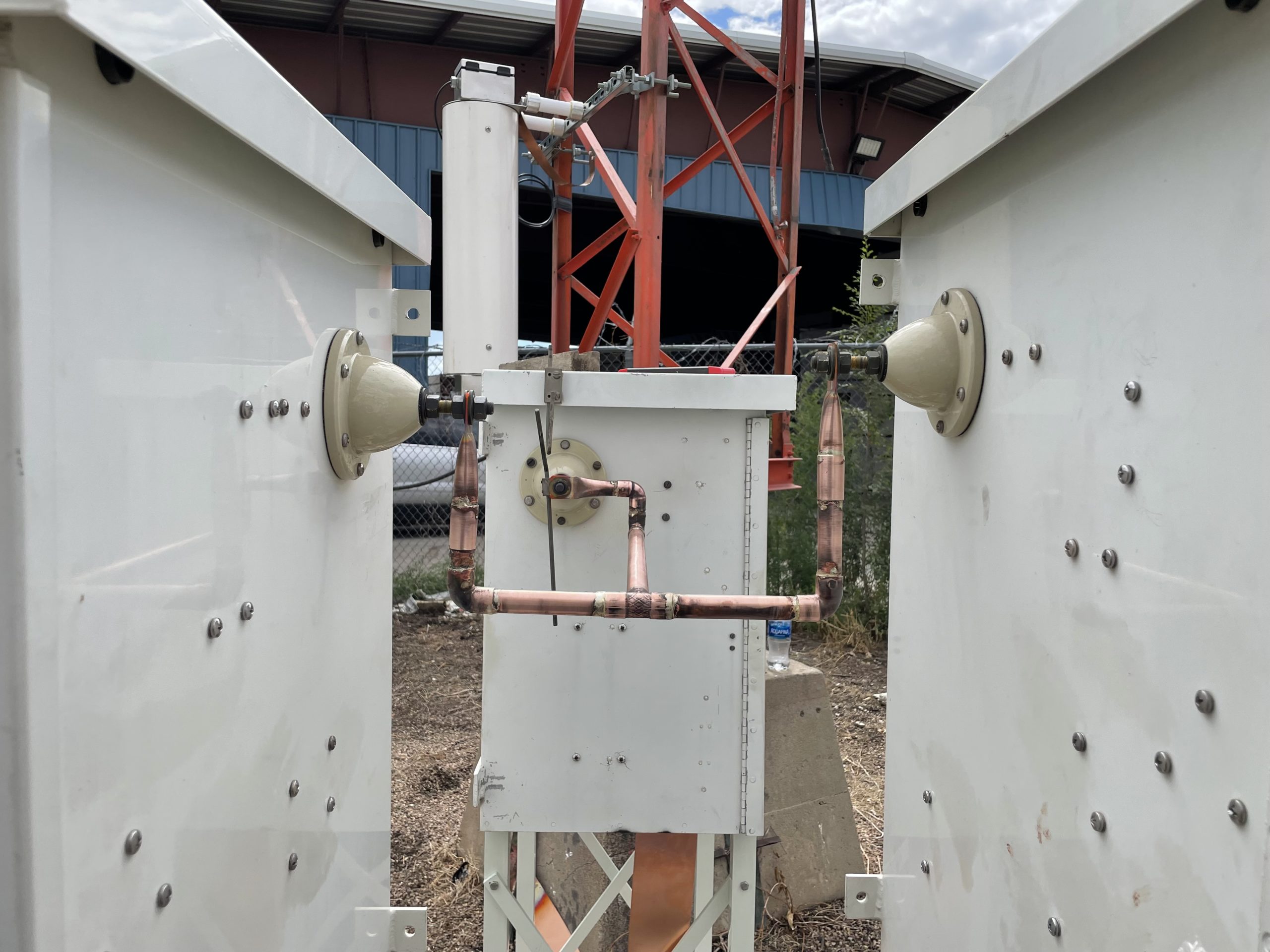
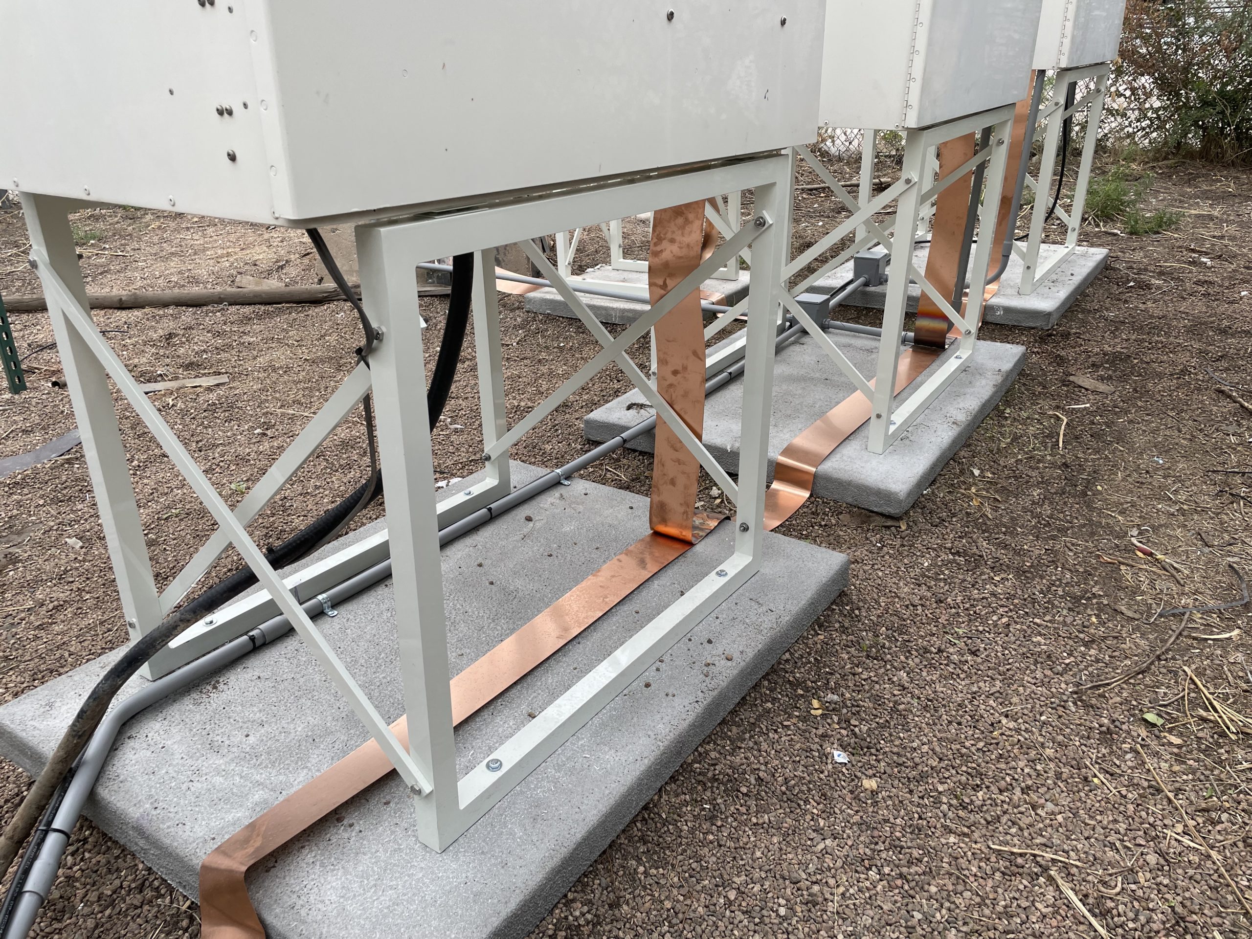
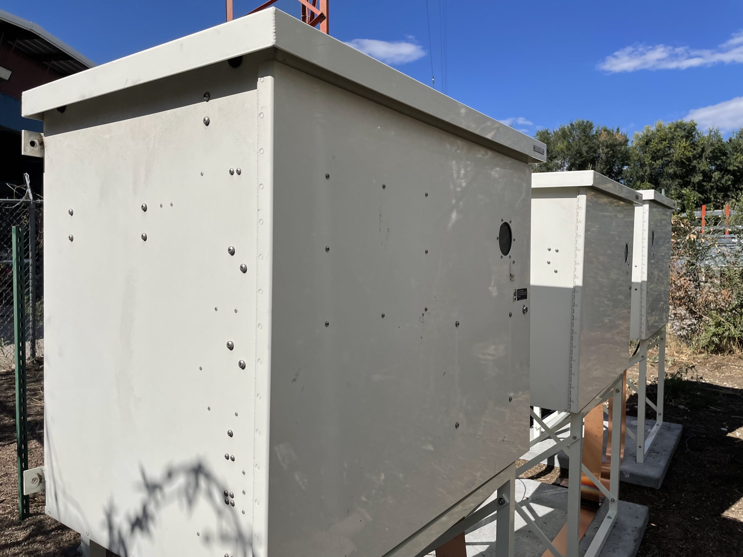
At that point, we decided that Thursday would be a transport and preparation day. On Thursday, we hoisted the cabinets into our engineering truck and a rental truck and hauled them over to the KGNU site. We set them on their mounting pads and bolted them down. Copper strap was run from the tower base to all the cabinets and connected. Three-quarter-inch copper tubing was cut, dry-fit and silver-soldered together connecting the three cabinets.
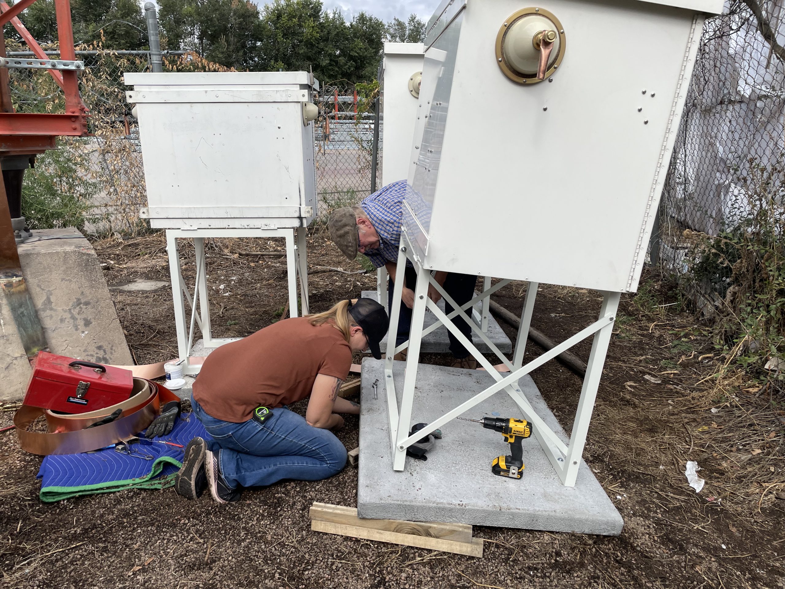
On Friday, we took KGNU down. Its existing ATU was removed from the Unistrut mounting and a Kintronics stand was installed before we moved it to its new location and mounting pad. Copper tubing was connected between the bowl insulator at the output of that cabinet and the input of the 1390-pass/1220-reject cabinet. We also removed the existing tower feed and connected a new, short piece of 3/4-inch feed tubing between the tower base and the input to the prematch cabinet.
At that point, all the cabinets were “in the circuit” and we were ready to begin final adjustments.
We started by touching up the filter tuning, focusing on the parallel tuned circuits in each, since those are the ones with sharp tuning (the series-resonant circuits tune so broadly that no readjustment was needed).
[Check Out More of Radio World’s Facility Showcases]
Shut that door!
Some redesign of the existing KGNU ATU network was needed, and we had all the parts on hand to get the needed match. Then our attention was turned to the KLDC input network, which was a real chore to adjust.
The 1220-pass/1390-reject cabinet is a combination filter/ATU. It includes a main 1220-pass/1390-reject trap, but no conventional auxiliary trap. Instead, to save space and cost, in his design, Cris series resonated the shunt leg of the 1220 ATU network on the 1390 reject frequency, providing a dead short to ground on 1390 at that point but the required negative reactance for the shunt leg of the lagging tee-network. Obviously, that complicates adjustment of that network, and it took several hours of tweaking to get it right.
We powered 1390 back up and had zero reflected power at the transmitter. Currents looked good, and clearly that station’s path to the antenna was in good shape. We had to run a temporary transmission line for 1220, and after connecting it, we fired up the ND-1 and found that it, too, had a good load.
Picking up tools and putting away test equipment, we thought we were at a good stopping place for the week, but then Cris went back into the transmitter building and immediately noticed that the reflected power was elevated on the KLDC ND-1, to the point that the transmitter had folded back its output power. What the heck?
Cris went back to the 1220 module, opened the door and observed nothing out of place. Back in the transmitter building, he saw that the reflected power was again low and the transmitter was no longer in foldback. Something was definitely changing in the 1220 part of the system.
On a whim, Cris went back to the 1220 module and shut the door, then immediately checked the transmitter. Aha! Reflected power was again high and forward power was folded back. Something was detuning when the door was shut.
Cris and KGNU engineer Eric Scace began looking at the 1220 cabinet and observed one piece of tubing that was about 2 inches from the plane of the closed door. With transmitters off, the VNA was connected and the impedance shift between open and closed door was observed. They temporarily replaced the tubing with a piece of 1-inch strap routed to have greater spacing to the door and the VNA measurements were repeated. A marked lessening of the shift was observed. A new piece of plated tubing was bent into shape and installed so that its spacing to the door was no longer an issue.
There was, however, still a significant shift in impedance between open and shut door. Cris speculated that the high-Q parallel resonant 1390-reject circuit was being detuned when the door was shut, and Cris and Eric confirmed that by measurement. It took some doing, but they were able to compensate for the effects of the closed door so that the trap was in perfect resonance with the door shut. This solved the 1220 impedance problem.
Back on the air!
At the end of that day (Friday), both stations returned to the air with KLDC operating under §73.1615(a). Stephen went home, leaving Amanda and Cris to finish up on their own.
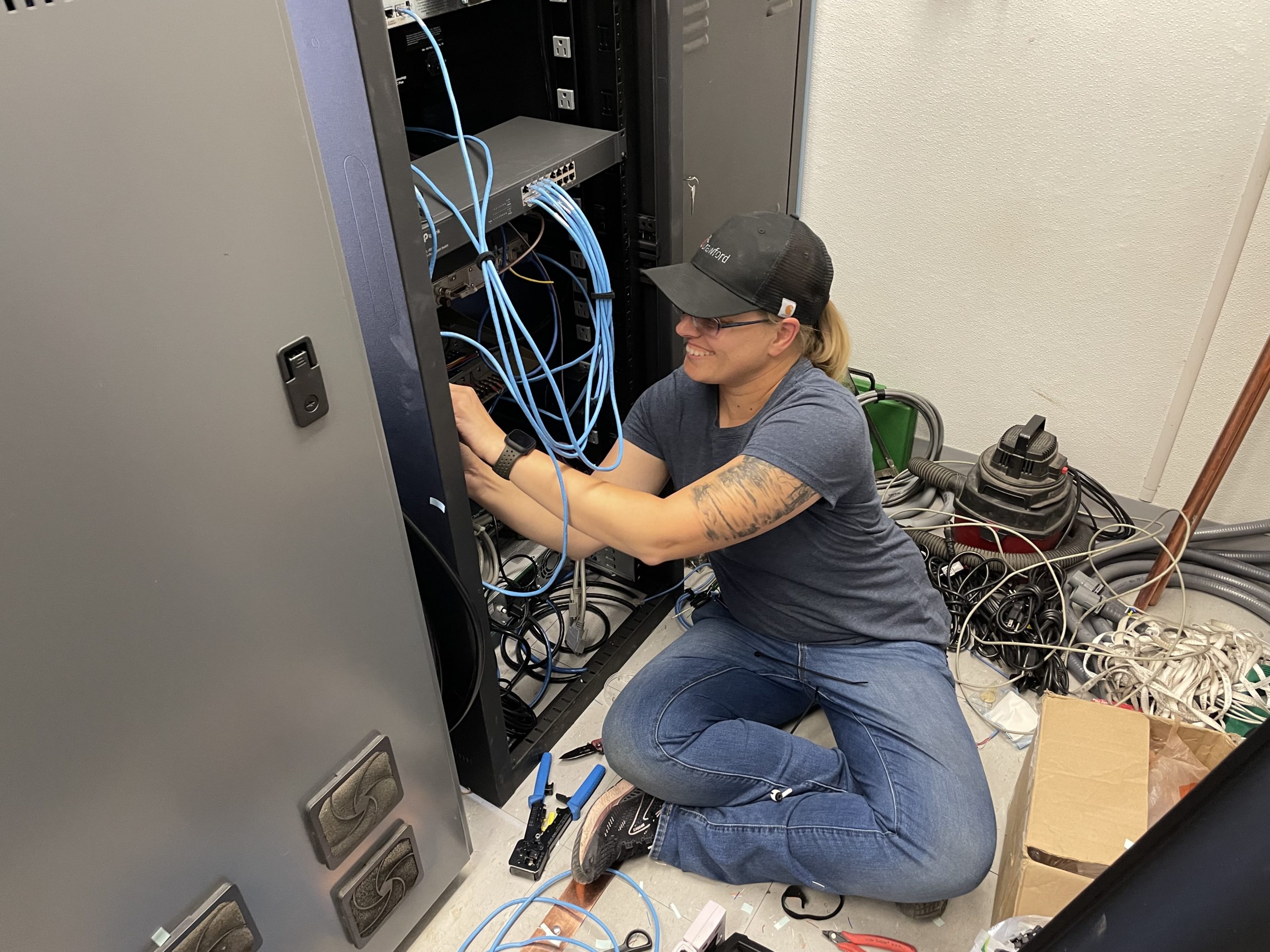
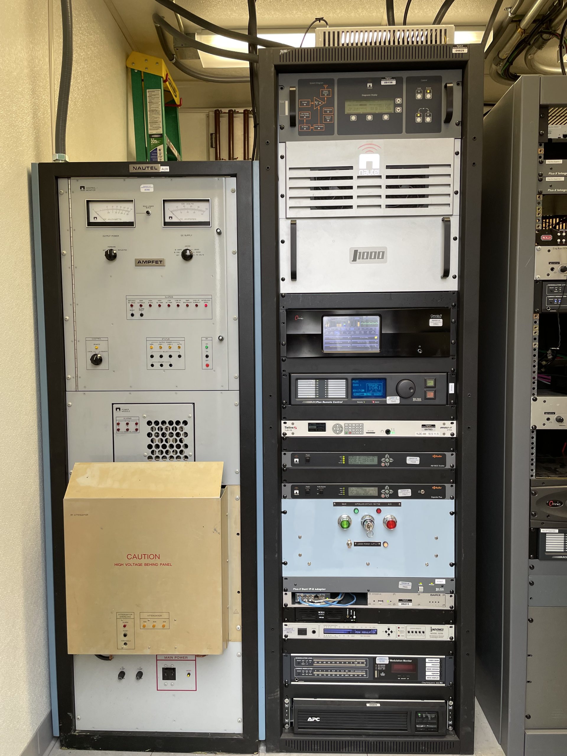
We still had a lot of work to do, though, including installation of conduit to the tower base and both filter modules, installation of the main transmitter, commissioning of the microwave link, setup of the LAN and router, adjustment of processing, and of course spectrum and IM product measurements. We got the measurements done first thing on Monday and got the license application filed.
The rest of that week we got the rest of the work at the site done, and by Thursday we were done, operating at full power on the main transmitter. An additional set of occupied bandwidth measurements confirmed that all was well.
It had been a long, hard journey, but we got it done. We moved KLDC to a new site, duplexing with a different host station and designing/manufacturing our own diplexer, all for about $20,000 in new cash outlay.
So how does it sound? It sounds great! Coverage is identical to the old Ruby Hill facility, and that J1000 with the Omnia.9 processor sounds like a big-gun station on the Denver radio dial. Our managers, staff and clients are happy, and we look forward to many years at the new site.
Our thanks to our new hosts at KGNU, to contract engineer extraordinaire Eric Scace, to Dr. Bobby Cox and our friends at Kintronic Laboratories for their invaluable help. We couldn’t have done it without you.
For others who may be contemplating an AM station move to another station’s site, that is a good option in many cases, especially when the cost of buying or leasing a land and putting up a new tower are prohibitive, as it often is. Collocating solves any number of problems, but it creates a few of its own.
“Rolling your own” as we did is not for the faint of heart. It takes experience, skill and a lot of work. A better option, if the budget will allow it, is to purchase multiplex filters already built up, tuned and tested. That’s certainly the way we would have gone had the numbers worked out.
But with the right skills and experience, building your own in the field can be done. We’re glad to have this project behind us.
You can see more pictures of this project here.