The author is a broadcast contract engineer who has a unique way of measuring the carrier frequency of the AM stations in his care.
Making off-air frequency measurements of AM broadcast stations can be a bit of a challenge.
Unless you are at the transmitter site and have a high-level RF sample of the transmitter output available, it’s unlikely that you can use a frequency counter to make the measurement. Another method has to be used to measure the low-level (millivolt-range) off-air signal. I have found an easy, “zero-beat” method that works reliably.
I use the following complement of equipment:
- Field intensity meter (such as PI FIM-21/41, RCA WX-2 or Nems-Clarke 120);
- RF signal generator with 0.01 Hz adjustability (such as Agilent E4430B);
- GPS-disciplined 10 MHz reference oscillator (such as HP Z3801A) and antenna;
- Loop antenna (such as Chris Scott LP-3).
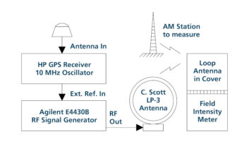
The physical setup is shown in Fig. 1, and the measurement procedure is as follows:
- Connect the equipment as shown. The loop antenna can be oriented in any way and should be placed about a foot away from the FIM.
- Tune the RF signal generator to the frequency of the station to be measured, then tune the FIM to that signal. It is not necessary to calibrate the FIM; it will only be used to receive the station and the actual field intensity reading is unimportant. You don’t even need to listen to the signal on the speaker or headphones. Set the meter to LIN mode, not Log mode.
- Disconnect the loop antenna from the RF signal generator or disable its RF output. Orient the FIM to maximize the signal coming from the station. Adjust the FIM’s Range switch and Gain controls for a mid-scale indication (3–6) on its meter.
- Reconnect the loop antenna or enable the RF output of the signal generator and adjust its output level so the meter swing remains within the limits of the scale. Set the RF output level based on the position of the FIM’s Range switch: for the 1 V/m range, start with –20 dBm; set it lower by 20 dB for each lower position of the Range switch. On my setup, I need around –10 dBm feeding the loop antenna for a usable indication on the FIM’s 1 V/m range. If necessary, change the RF signal generator’s frequency up or down by a few Hertz to see the meter swing back and forth due to the beat frequency.
- Adjust the RF signal generator’s frequency to zero-beat the station so the meter swing is minimized and eventually stands still. Go right down to 0.01 Hz steps. Take your time as you get near the exact frequency, as the meter will be moving up or down very slowly. Make sure you’re not at a maximum or minimum of the zero-beat cycle. You want a position where changing the frequency up or down by 0.01 Hz causes the meter indication to reverse direction, indicating you’re as close as you can get. With practice you can dial in the exact zero-beat frequency in less than 30 seconds. Read the station’s exact carrier frequency on the RF signal generator.
Stations running IBOC, most of which are locked to a GPS reference frequency, are usually very close to their assigned frequency, within 0.1 Hz. Most modern analog transmitters will show some seasonal drift with temperature.
I am currently checking the carrier frequency of four local stations. The IBOC station (that is not using an external GPS antenna) has drifted up 0.04 Hz over five years. The others tend to move up or down by as much as 3 Hertz as the equipment temperature changes. The FCC rules require the carrier frequency to be within +/- 20 Hertz, so a few Hertz won’t matter.
[Subscribe to Radio World Engineering Extra]
I’ve been using this method for more than eight years with results that match or exceed the commercial frequency measuring company’s reports.
I have the equipment listed above, but you can make substitutions if necessary. For example, in place of the Chris Scott loop antenna, a couple of clip leads and a series 30-50 ohm resistor can be used to form a loop that can be loosely draped on top of the FIM’s loop antenna. Even a short whip antenna can be used on the signal generator if the FIM is close enough to it.
An RF signal generator that lets you specify a frequency within 1 Hz or better can be used as long as it can utilize a 10 MHz reference signal. The carrier frequency you measure will only be as accurate as the equipment you have available to measure it with.
The 10 MHz reference signal could come from a rubidium oscillator, which has been adjusted to zero-beat a GPS-disciplined oscillator (GPSDO). These can often achieve accuracies of 0.0001 Hz on the 10 MHz signal.
An AM radio with a VTVM or DMM on its AVC line can also be used as an indicator if you don’t have an FIM.
RW welcomes your Tech Tips, email us at [email protected].
The author is an amateur radio operator (WA1MIK) and FCC licensed contract radio engineer in Southern Connecticut. Email him at mailto:[email protected].