This article continues a discussion of AM DA maintenance; here’s a link to the first part.
In our earlier exciting episode, we promised a real-life story. There are many, but here is my favorite:
Years ago I was doing contract engineering work for KKCQ(AM) in Fosston, Minn., about 140 miles from home. It was nondirectional day, with a three-tower directional antenna system at night.
I just happened to be there one morning doing maintenance in the studio/transmitter building when the 5 kW AM transmitter shut down. I was pushing the plate-on button when a man walked in and said we should go out to the parking lot.
There it was: His potato chip delivery truck had snagged a guy line and pulled the center tower down onto the parking lot and beyond.
Trucks like that are large because potato chips take up a lot of space while weighing next to nothing. The downed tower was just 197 feet so there wasn’t a resounding crash when it fell. Astoundingly, no one was hurt, no vehicles were hit and there was little other damage.
The first order of business was to call the power company to have guy lines carefully lifted from overhead power lines. You guessed it, that now-horizontal tower was the non-directional day tower for the station.
Needless to say, the station was off the air. What to do about putting the station back on?
Well, two of the three towers were still standing. I used some #8 electrical wire to make changes in the phasor cabinet, sending all power into the north tower. The tube-type transmitter ran nicely at 1,000 watts even with some VSWR. More power was not going to happen that day because the antenna coupling network was designed to put no more than 1,000 watts into that tower.
On the positive side, I was the “hero of the day” because the station was returned to the air just in time for Paul Harvey’s noon news and commentary broadcast.
D VS. ND
In the final analysis, KKCQ ownership looked at losing a tower as a blessing.
The 2,500-watt night directional pattern, pointing north, served very few listeners while putting noticeable nulls in populated areas of town, just to the west.
They elected to go non-directional day and night. The station returned to 5 kW on the north tower during the day with 90 watts at night. That 90 watts is sufficient for the community and the directional nulls are gone.
They sold the phasor and antenna monitor. With that money, and insurance compensation, they had a good start to building an FM station. They’ve not looked back and have lived happily ever since.
KKCQ ran a Gates BC-250GY AM transmitter at 90 watts during night hours, which was becoming expensive to maintain. Replacing it with a Broadcast Electronics AM-5A transmitter was a wonderful choice. That 5,000 watt transmitter will run with good sounding/clean audio at the 90 watt night power level. The design is perfect for that kind of drastic power cutback. Most transmitter designs can’t give good audio performance at less than 10% of rated power output.
Another station I worked at uses that same model BE transmitter for 5 KW day and 30 watts at night. It also sounds great at both power levels with no interruption in audio as it slides between power levels.
RF Contactors
Minnesota is known for actual winter temperatures that dip to 40 below zero at times. Lowest overnight temperatures usually coincide with sunrise, a worst-case scenario. That’s when directional AM stations switch from night to day patterns.
Most contactors/RF relays have solenoids (AC magnets) to pull a contact bar. They get sluggish under cold weather conditions, as you can imagine. Some stations use 100-watt incandescent lamps or electric heaters to keep tower shacks warm in winter.
If you do this, it is best to put any heat source below an RF contactor so the heat will rise into the contactor. Do it in a safe way so a fire is unlikely to start. RF contactors are wear items and will need repair from time to time.
The stations I worked on usually had a spare contactor on the shelf because failure is inevitable. When replacing a contactor, I would take the failed one to the shop for repair. I would then put them in plastic bags and back in stock, at the transmitter site, for the next incident.
Tips & Tricks
Use 3M Scotch Brite to clean tarnished RF contacts. Tarn-X liquid is normally used in the home to clean silverware, but works equally well on silver-plated contacts.
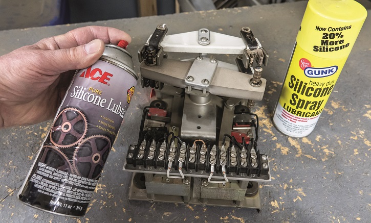
My experience is that pure silicon lubricant spray works well to keep things moving. It makes sliding contacts slippery and adds some measure of protection against future corrosion. My sources for that are Ace Hardware and stores that sell Gunk brand products.
Yes, the contactor shown above needs cleaning of its contacts before lubrication and going into service.
Voltage Can Be Low
Towers in an AM directional array are often hundreds of feet from the transmitter building. That means power to the solenoid coils might be less than the rated 208 to 240 VAC.
About 212 volts is considered normal for 208 three-phase power nowadays, but it is still less than a full 240 volts. At four amperes of solenoid current, the voltage at a tower could drop to as little as 190 volts, hardly enough to make a contactor switch reliably.
One cure is to use larger-diameter wire to feed the towers. Another is to install a low voltage transformer, wired as a “boost.”
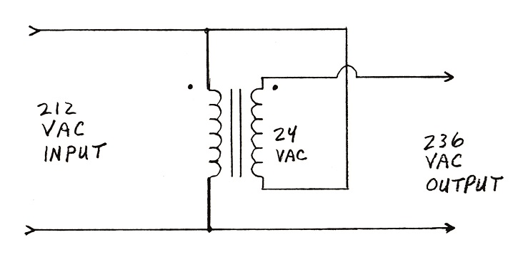
With a 24 volt transformer secondary winding wired in phase and in series with the incoming power, the 190 volts could rise to 214 volts at a tower. Dots on the schematic are for polarity of the windings.
Out of phase, the available voltage will be 24 volts less. You likely won’t use a 24 volt transformer for day and another for night at each tower. Instead, a single higher-current transformer could do the work for all towers, switching to both patterns.
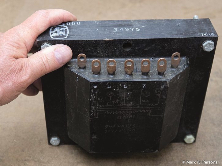
Transformers of this nature need to be installed in a safe location. The most common place is inside a phasor cabinet which is interlock-protected. Fig. 3 is a transformer from my parts box that can supply 22 volts at 21 amperes. It weighs in at 26 pounds and is enough to help five RF contactors at four amperes each. This one also has more transformer taps for lower voltages.
A three-tower directional would likely need 4 amperes/contactor x 3 towers = 12 amperes of required transformer secondary current. RF contactors in the phasor would be getting the full normal voltage anyway so they don’t need a boost because they are at room temperature and there is less chance of them sticking.
Take Notes
Rarely did I go to a transmitter site without finding something that needed attention. I used a piece of paper, in a shirt pocket, to write a few words, jogging my memory to purchase or bring a repair part on the next visit.
Don’t let things slide. Keep sites clean and in good repair. Throw out failed parts and only retain usable ones.
Metering
Not all RF current meters are alike. Fig. 4 shows a thermocouple RF ammeter.

This one is classified as having an “expanded scale” so it is FCC legal to read currents from 4 amperes to 20 amperes.
Less expensive “square law” thermocouple ammeters are only good to read down to one-third of full scale. That means a 20 ampere meter is only accurate above 6.66 amperes, as per FCC rules. Check meter specifications to be sure.
You’ll note the meter needle is not sitting exactly at zero. Best to tap on the side of the meter while adjusting the zero set screw on the front to achieve an exact zero when no current is flowing in it. Meter accuracy after that will depend on this easy first step.
Take readings with thermocouple meters during a pause in modulation. That is when the indicated current will be at its least. An FCC inspector will do that too.
Delta Electronics makes transformer coupled ammeters (TCAs) for measuring RF currents in AM antenna systems.
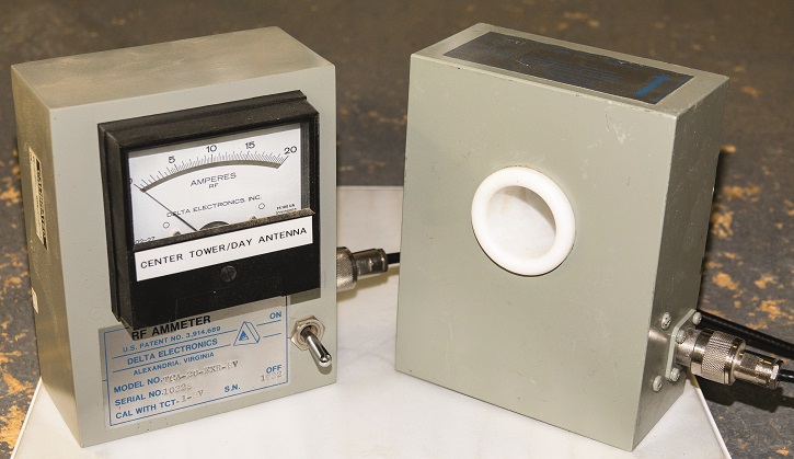
These use a toroid to sample RF and then diodes to turn it into DC to drive a meter. Those are good down to one-fifth of full scale. Their mirrored scales help give better accuracy when you look at one, lining up the meter needle with the needle in the mirror behind.
Delta also has meters with digital readouts, giving an astounding 100:1 ratio between its highest and lowest current readings at 2% accuracy. AM pioneers never even dreamed of that!
For those who are unfamiliar with amplitude modulation, an AM station’s average power increases 50% when 100% modulated with audio. Traditional thermocouple RF ammeters will read that additional power, but Delta meters do not.
However, they will show carrier shift, which is the result of transmitter power dropping a few percent as the transmitter’s modulator draws down the supply voltage during high modulation conditions. It can also happen when the transmitter has a weak PA tube. Solid-state transmitters typically have little or no carrier shift.
Meters were once required at the base of each tower to read current. The readings could then be compared as a “ratio” to the reference tower. I say ratio because they all go up or down together as transmitter power changes. The FCC deleted that rule because antenna monitors do the same thing with a lot less hassle.
If the system you are working on has base current meters, I recommend you take readings for future reference. Compare them to the original proof of performance as a double check.
RF Protection
Fencing to keep people away from radio frequency radiation has been required for many years (Fig. 6).
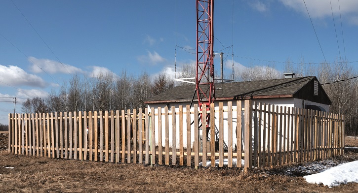
Keep fences in good shape; it’s the right thing to do. It’s also a liability issue. You don’t want to be held responsible, in a court of law, when someone claims they were injured because a fence was inadequate.
Monitor Points
Friend and fellow RW contributor Buc Fitch penned an informative article on field intensity measurements about 15 years ago. That information will help guide anyone in getting reliable field intensity readings. The text is at https://www.radioworld.com/miscellaneous/field-intensity-measurement-methodology.
And, of course, I am not the last word on this subject. For serious changes or repairs to an AM directional, it is best to call a consultant.
In sum: Think the job through to save yourself time and trouble. It makes perfect sense.
The author built four new AM directional systems, from the ground up, using only schematic diagrams and parts in his time as a broadcast engineer.
Comment on this or any article. Write to [email protected].
Mark Persons, WØMH, is an SBE Certified Professional Broadcast Engineer and was SBE Engineer of the Year in 2018. Mark is retired after more than 40 years in business. His website is http://www.mwpersons.com.