![]() Read other articles in this series: Pi for Everyone and Everything and Get Email Alerts From an RFEngineer’s Watch Dog Receiver.
Read other articles in this series: Pi for Everyone and Everything and Get Email Alerts From an RFEngineer’s Watch Dog Receiver.
Nowadays, many people are playing with the Arduino (and clones) and the Raspberry Pi (and clones), sometimes known as Single Board Computers or SBCs. We’ve even heard rumors lately that they’re starting to show up in some of our broadcast equipment, hidden and embedded down inside the case.
Each has strengths and weaknesses. There’s no shortage of opinion about which is better. If you want mine, the Arduino is better for small machine control applications, and the Pi is much better if you need networking, a GUI desktop, and the buzzers and bells. The Arduino isn’t nearly as powerful, but it’s ideal for a dedicated process controller. Because the Pi is a full-blown (if miniaturized) computer, it’s not as suited for real-time processes. In the end, the choice is yours.
The key question for us is whether it’s reliable. You might say, “I can maybe see a print server or ‘smart’ wireless access point in my studios, but will they work at a remote transmitter site in a corn field?”
Yes, provided you protect the inputs and outputs (“I/O”). Modern microprocessor chips are quite reliable, if you respect their limits. Even if your transmitter is a newer model with logic inputs and outputs, you shouldn’t just connect it directly to the pins on the SBC. You’ve also got to watch your input voltages, regardless of surges. For example, if your SBC’s processor chip is running at 3.3V and you connect 5V to one of the inputs, bad things will happen.
There are third-party I/O boards available for the Pi (traditionally called “hats”) and the Arduino (“shields”). They’re a good place to start experimenting, but most aren’t suited for hostile environments. One analog I/O board that we purchased only had 1K surface-mount resistors between the input terminals and the pins on the A/D chip. That did provide a little protection, but there was no way it would handle a strong surge.
WHY USE AN SBC?
The example that I’ll show you in this article could admittedly be done with a recent-model remote control with network connectivity. The better remote controls — and for that matter, many of the latest transmitters — can now send email or text, offer SNMP control and more. But the biggest advantages to the SBC revolution are:
- SBCs are ridiculously cheap. You can buy several and keep spares on hand.
- They’re ridiculously small. You can even get nice cases to make your work look pretty.
- There is plenty of information online; code samples, “how tos” and more. You will probably be able to find an existing project that will do what you want with only a bit of modification.
- You can give your equipment precisely what it wants with “smart” logic. For example, you may need to send your transmitter a momentary command when a long-term fault occurs, but the faulting device only provides a constant closure. (The little Adafruit Itsy-Bitsy, which is Arduino-compatible, is ideal for this, by the way.)
- If your SBC has network connectivity (the Pi does by default; you can add it to the Arduino), it can send email, and/or you can log into it remotely to check on things.
Besides, what if your existing remote control is an older model? What if it has just been destroyed by lightning and you need something right now while you wait for a replacement? Most importantly, what if it’s a special case that your existing remote control just doesn’t address as well as you’d like? (See again advantage #4 in the list above.)
AN EXAMPLE: THE GENERATOR MONITOR
This is an actual Raspberry Pi 3 B+ project that I’ve installed at one of our big FMs here in Alabama. We use a Nautel GV40 transmitter at both of our 100,000 watt FM sites, and for STLs we have dedicated wireless data links. This is ideal for “anywhere access,” because we can (carefully, with a good firewall and some port forwarding) reach our sites over the internet.
Briefly, here’s the background: Both sites are located at the top of a hill in relatively remote areas. The dirt roads tend to wash out after a storm or have fallen trees block access. The public roads to the main gates are paved, but they can also be blocked by flooding and fallen trees. In a severe storm event, I’m probably on generator, and it’s going to be a while before I can access the site to refuel the generator. To stay on the air, I want to lower power to reduce the generator’s fuel consumption.
Our remote control units are supposed to be capable of doing what I want, but “programming” them is quite time-consuming. It’s not easy to test your work either, whereas with a Pi or Arduino, I can easily simulate the inputs and confirm that it does what I need.
Long story short, given my background as a programmer, engineer and inveterate tinkerer, I opted for the Pi at one of these sites — less than $50 from Digikey with the “Noobs” Raspian operating system ready to go on an SD card.
The second site uses an Arduino-type processor, and will actually raise and lower the transmitter power automatically. I use a laptop running Linux to monitor the Arduino, and it sends the email. But that’s for a future article; for now let’s just look at using a Raspberry Pi as a standalone monitor. If one of the I/O pins goes low, it will send an email. I’ve set it up so that, if the generator starts running, the program running on the Pi will send a warning. Likewise, once the generator stops running, I get another email. I can then choose to go into the transmitter remotely to lower the power, if I so chose.
LIMITING I/O CURRENT
The key to protecting your Pi or Arduino is guaranteeing that the inputs never see a “hostile” input. That’s the ideal, anyway; we can at least add enough protection to cover us in most cases. This project uses the K827-PH, an opto-isolator available from most supply houses, including Digikey and Mouser. These are typical LED-in, transistor-out units, with four isolators in a single 16-pin DIP package. We only need one opto for this example, but the others are available for later expansion.
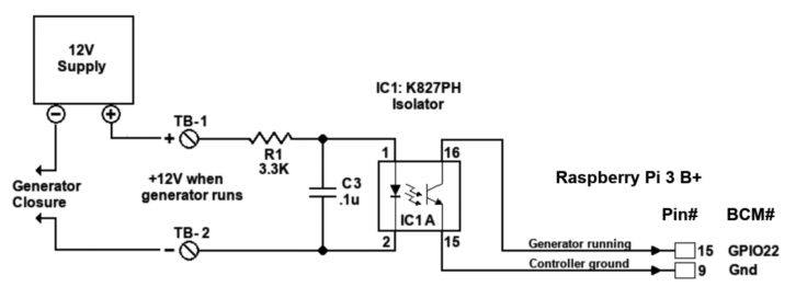
Fig. 1 shows the basic circuit for this discussion. This is a simplified version of what I’ve done at the site mentioned above. The whole purpose of isolation is isolation, so I don’t connect the input on the Pi directly to the generator’s “run” contacts. I also do not take the 5V supply from the Pi; that would defeat the purpose of isolation. Instead, I’m using an external 12V supply (in actuality, a simple 12V wall wart) which goes through the generator’s normally open contacts, through a 3.3K resistor, into the K827 isolator.
Look closely at R1 and C3 at the opto’s input. I’ve determined that this is all the protection needed for this particular site. If you have one of those sites that attracts everything from lightning to extraterrestrials with funny hats, you should improve this. Make the capacitor larger. Add a varistor to ground to clamp any high voltages. Split R1 into two 1.5Ks, instead of a single 3.3K, with an extra capacitor to ground in the middle. Add a ferrite or RF choke on the input. I will leave this up to you.
If the generator starts, its normally-open contacts will close, causing about 3 mA of current to flow through the isolator’s LED. This turns on the transistor, which pulls pin 15 low. All we need now is a little program that will check that pin at intervals (I’ve chosen 60 seconds).
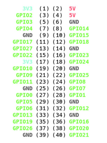
Fig. 2 is the pinout of the 40-pin IDE-style connector provided for I/O on the Pi. At this point, the Raspberry Pi’s documentation can confuse you: there are actually several different naming and numbering conventions for the 40-pin IDE style connector that is provided for I/O. The python library that I’m using wants the “GPIO” numbers. Note that each input can also be assigned different uses, depending on what you’re doing. For this article, we only need GPIO 22 as an input, which maps to pin 15 on the 40-pin connector.
You can download the ready-to-run python program here. Pull it up in an editor and change the email addresses, password, the email server and port numbers as needed. Once you’re done, save the file as genwatch.py, then copy it onto your Pi. In a terminal, in the same directory as that file, enter the command
“chmod +x genwatch.py”
to make the file executable. Now you can run it by entering
“./genwatch.py”
at the terminal prompt, while still in the directory containing the file. The program will continuously check the assigned pin at 1-minute intervals, sending an email if the generator’s status changes. Press CTRL-C to stop the program.
To test it, momentarily short pin 15 (GPIO22) to pin 9 (ground) on the 40-pin connector. You can use a clip lead or a small jumper wire — but be careful! Some of the other pins are directly connected to the power supplies, and you can damage things if you accidentally put 5V on a 3V input, or ground one of the power pins. The classic boo-boo is accidentally shorting pin 1 to pin 2 on that 40-pin connector; you’ll be connecting the 3.3V supply directly to the 5V! You really don’t want to do that one.
I’ve commented the program for you. Python will ignore anything after the hash (#), so comments are a great way to explain what the code is doing. Again, you will need to put in a valid email address and password, as well as the recipient’s email address and the address of your email server. These are also noted in the program.
Get a Raspberry Pi and play with this. You will want the Pi and the Raspian operating system, which is available for download or pre-installed on an SD card. Python will be included with the standard Raspian Linux operating system, so you should have what you need.
More information is available online. You can do a Google search for “Raspberry Pi python” to see a bunch of examples. There are a host of forums available online as well, from the “official” Raspberry Pi forum to special forums sponsored by vendors like Seeed Studio, Adafruit, and others.
If you’re feeling experimental, here’s an idea: Refer to Fig. 2 for the pinouts and try reassigning that “genrun = Button(xx)” line in the program to different GPIO numbers. Then ground those pins; the emails should be sent. For a more advanced example, consider using one of the spare optos to monitor the 12V wall wart itself, and send an additional email if the 12V power supply should fail. In any event, have fun!
Stephen Poole, CBRE, AMD, is chief engineer at Crawford Broadcasting Company in Birmingham, Ala.
How do you use an SBC at your workplace? Tell us at [email protected].