The 1950s was a fantastic era for industrial design.
Everything seemed to have a distinct personality, color and purpose. Automobiles made the boldest statement with towering tail fins, but table radios were not far behind.
Take this 1955 Westinghouse Model H-550T5 clock radio. While its bright shade might look like something Elvis Presley would have picked off the showroom floor, the factory color palette officially called it “rose.” Whether you call it pink or rose, it caught my eye (Photo: Gloman Westinghouse #1).
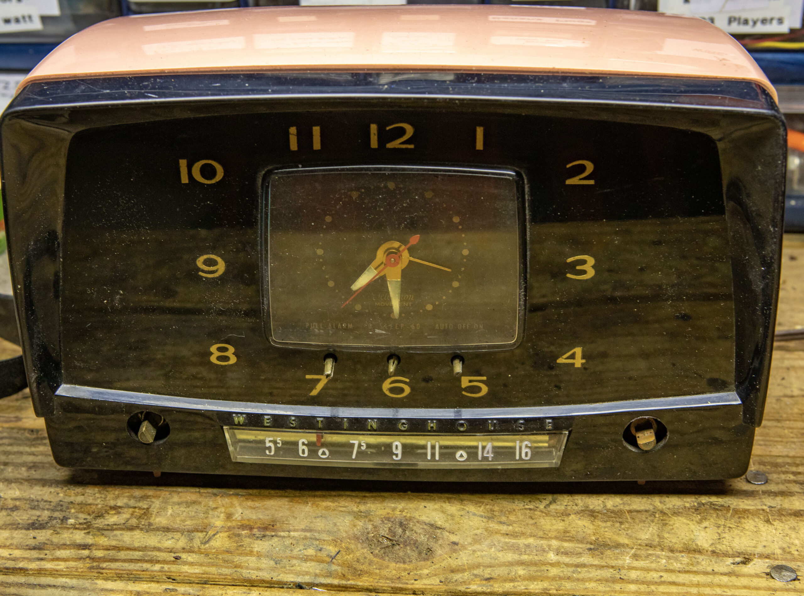
I found the unit on Facebook Marketplace. The H-550T5 was missing its primary tuning and volume knobs, and two of the three smaller black clock controls were gone. The rose cabinet was in solid physical condition and the clock mechanism ran, but the radio “just hummed,” according to the seller’s listing. I told him it probably hummed because it did not know the words, but he did not appreciate my bench humor.
Westinghouse produced the series in four colors: the H-547T5 in gray, H-548T5 in ivory, H-549T5 in green and my model in rose. Mechanically, it is a classic All-American Five superheterodyne. The series filament string consists of a 12BE6, 12BA6, 12AV6, 50C5 and 35W4, which together drop 121 volts across the line.
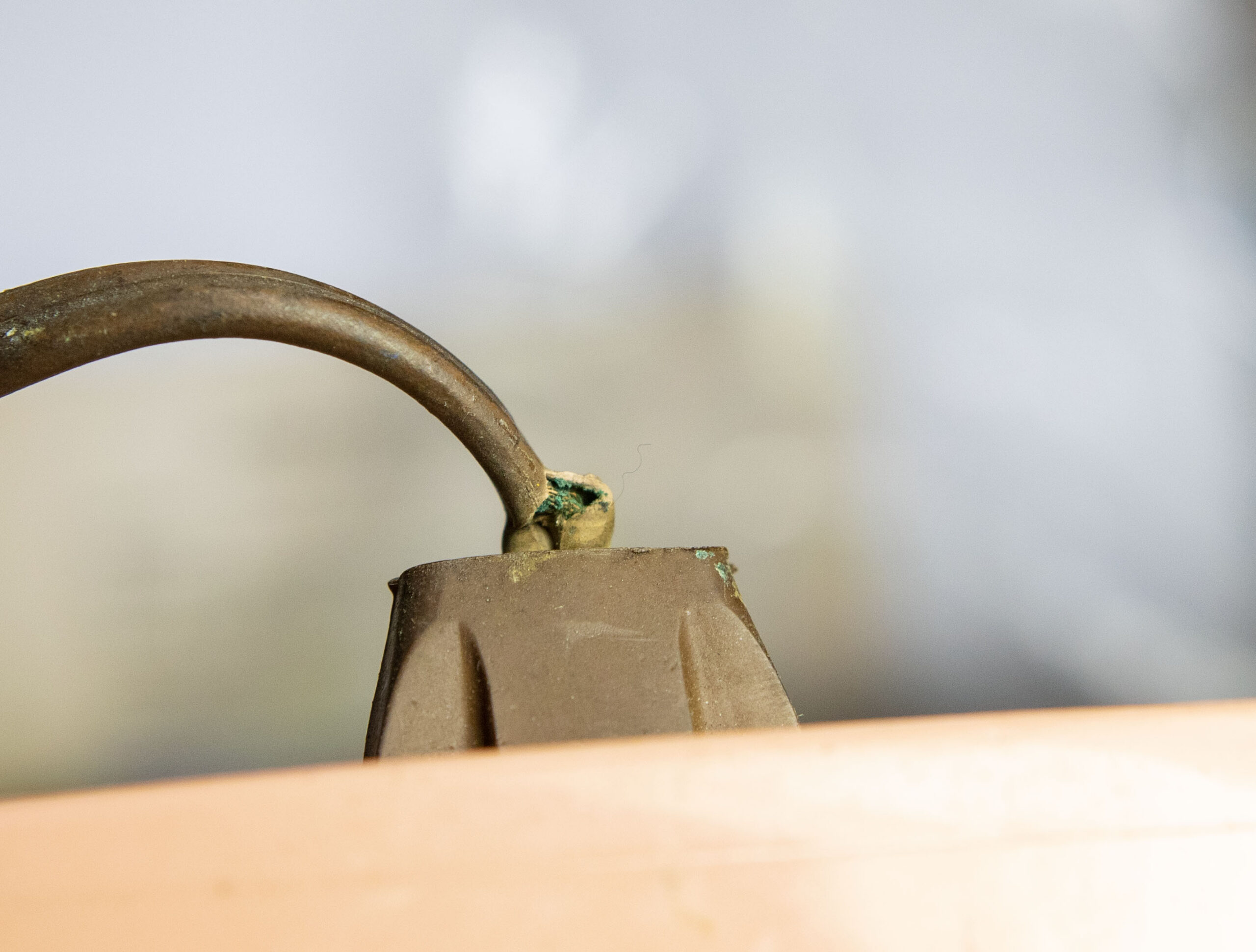
Looking at the rear cover, I noticed the original line cord was severely frayed and bent where it entered the chassis. Disassembly was straightforward. Backing out a 3/4-inch self-tapping screw at the bottom of the cabinet and four 4.25-inch Phillips-head screws separated the rear cover from the faceplate, without requiring the removal of any front controls.
After pulling schematics from RadioMuseum.org and reading up on the chassis history online, I pulled the chassis to inspect the interior.
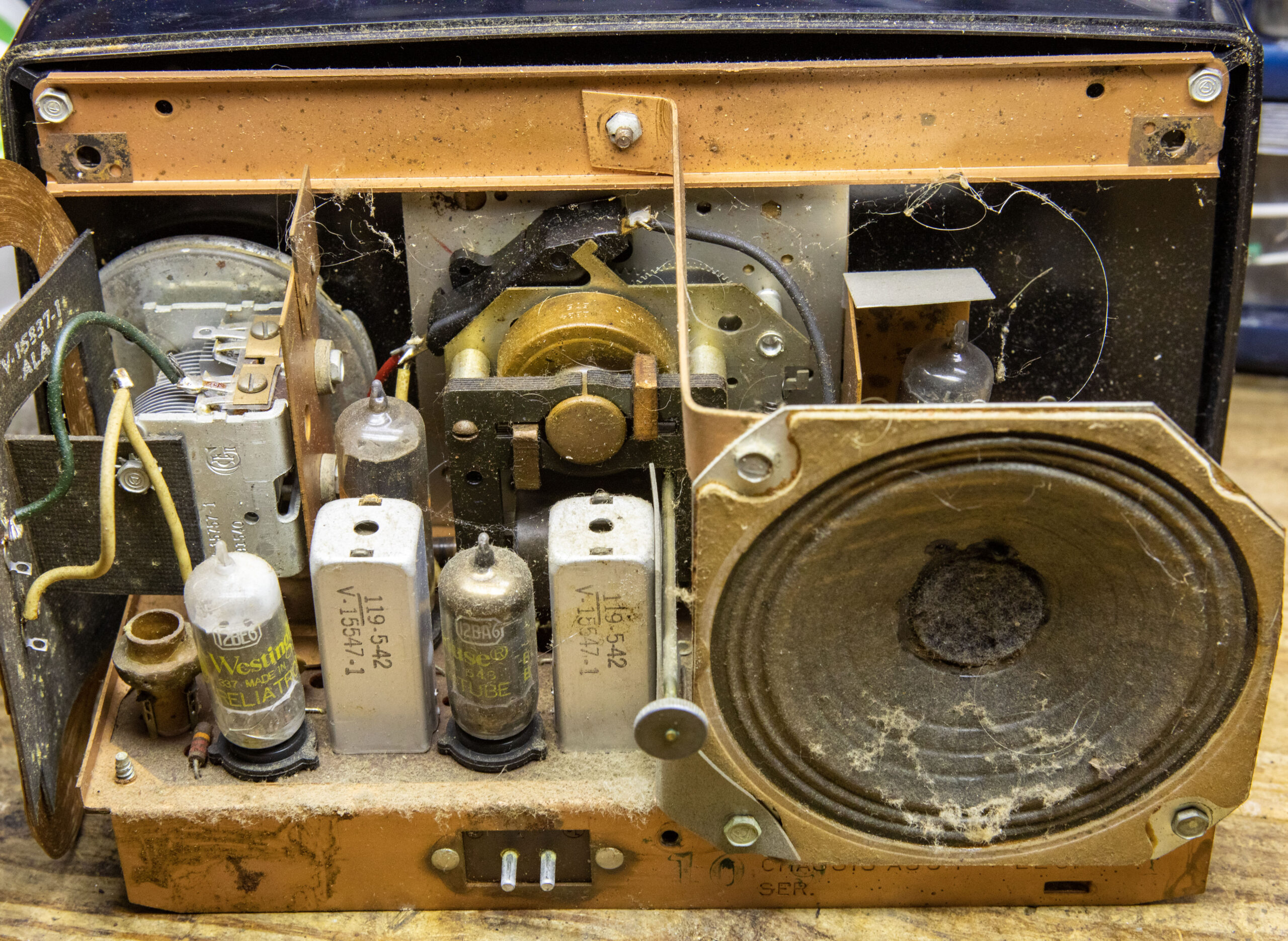
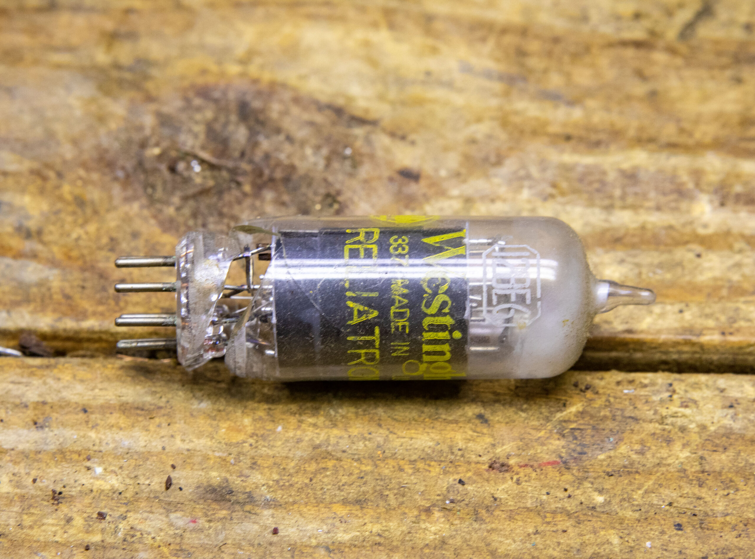
The visual check quickly turned up the first obvious defect: The tube on the far left was cracked and cloudy from air intrusion.
Flipping the chassis revealed the point-to-point printed wiring board, along with the original multi-section electrolytic can and a 47 µF paper capacitor. At more than 70 years of age, the filter capacitor was well past its reliable service life. A telltale coating of white residue on the cardboard sleeve indicated that the radio had been stored in a damp environment, a diagnosis reinforced by surface rust along the volume and tuning D-shafts. Dried-out, leaky electrolytic filter capacitors are almost always the culprit behind a loud 60 Hz hum, as they can no longer filter AC ripple.
The original electrolytic unit contained two 50 µF sections rated at 150 volts. Sharing a common negative black lead, the positive lead for C1A connected to a yellow (formerly red) wire, while C1B tied to a green (faded to blue) wire. Because both sections share the same capacitance and voltage rating, lead orientation between the two circuits is interchangeable.
Given standard component tolerances of plus or minus 20%, modern 47 µF capacitors make an ideal substitute for original 50 µF ratings. Purists often prefer restuffing the original cardboard cylinder with new miniature radial parts, but since this under-chassis work remains hidden from view, I installed two discrete 47 µF 160-volt axial capacitors. I also swapped out the .047 µF paper capacitor for modern film.
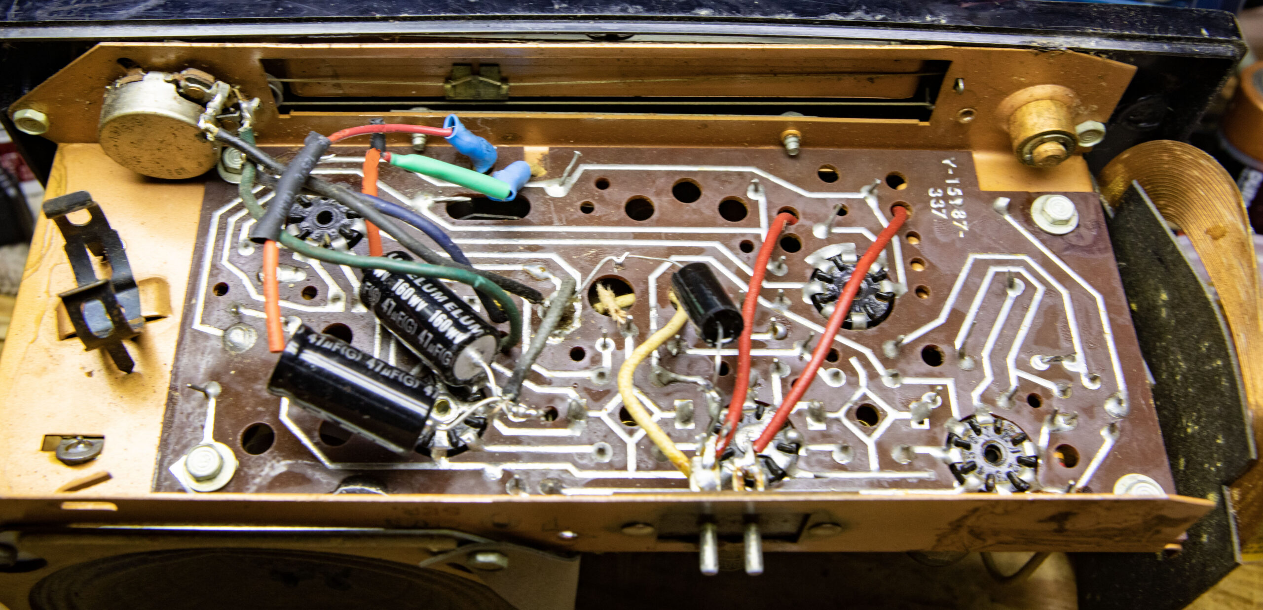
The final capacitor to be replaced was C6, a .01 µF 600-volt unit tucked behind the 12AV6 first audio/detector tube.
The remaining capacitors in the circuit were mica types, which rarely drift or break down. To be certain, I lifted one lead on any component that looked questionable and verified its value with a digital capacitance meter.
[Related: “Let’s Discuss the Power of Capacitors”]
Vacuum tubes can be unpredictable. I have seen original tubes operate within spec for seven decades, and I have seen new-old-stock tubes fail within a week. As a kid, I was captivated by the local TV repair technician who would visit our home to service our 1967 Zenith color set. He seemed to diagnose problems by instinct alone, swapping tubes directly from his caddy without testing them first. I still have those old burned-out tubes in a box!
Rather than shotgunning parts, I cleaned each tube pin and checked every envelope on my mutual-conductance tube tester, replacing only the fractured 12BE6 converter. The other four tubes tested strong and will comfortably see their 71st birthday. All seven carbon-composition resistors were metered and measured within their marked 10% tolerances.
With the passive components refreshed, it was time for power testing. Anyone who has worked on transformerless AC/DC radios knows never to touch an exposed metal shaft on a live set due to shock hazards. While this particular chassis configuration is safer than earlier hot-chassis designs, safety precautions are essential. I keep my radios on a dry wooden bench, wear rubber-soled shoes, remove all metal rings or watches, isolate the bench using an isolation transformer and keep plastic knobs pushed onto bare control shafts.
Because the Westinghouse had arrived with bare metal D-shafts protruding 3/8-inch, I pressed on a pair of temporary plastic knobs scavenged from an old Crosley before powering up.
Rather than trust the frayed original power cord, I attached a temporary two-conductor cheater cord for initial bench testing. As I often remind fellow collectors: Never plug an unrestored vintage radio straight into a 120-volt wall outlet. You have no way of knowing how an unserviced set was stored or whether a previous owner botched a repair. Novice sellers almost always offer to plug a radio in to demonstrate that it turns on, but feeding full line voltage into dried-out capacitors can instantly short a power transformer or smoke a rectifier.
My standard operating procedure is to run all vintage equipment through an isolation transformer paired with a variable autotransformer (Variac), bringing voltage up in small increments while monitoring current draw.
Dial lamps typically glow first, followed by the tube heaters. Because this Westinghouse model does not include dial backlighting, there were no initial visual clues. Unlike standard table radios, the volume control on this clock radio does not incorporate a rotary power switch. Line power is routed through a three-position slide switch on the front: Auto (which allows the mechanical clock mechanism to trigger playback), Off and On. The left-hand slider arms the alarm buzzer, while the center switch operates a sleep timer.
At roughly 80 volts AC on the Variac, the clock’s sweep second hand started moving and the tube filaments began to glow orange. At 100 volts, audio hiss appeared in the speaker. Turning the dial brought in local AM signals with substantial volume, though an annoying buzz quickly emerged. Inspection revealed that the original glue securing the paper cone to the speaker basket had dried up and separated, allowing the cone to rattle against the frame. A thin bead of Tacky Glue held in place with small spring clamps resealed the suspension and eliminated the distortion.
Clock movements can be a headache to revive because of dried oil and fine gear teeth. In many cases, past cleanings with harsh solvents stripped away factory lubricants. Fortunately, this Telechron motor ran smoothly, was not starved for lubrication and maintained steady time.
With the chassis running properly, I soldered in a new reproduction power cord, cleaned the cabinet and tracked down five appropriate replacement knobs. A damp melamine sponge removed decades of nicotine film from the plastic. Buffing the housing with Novus No. 2 fine scratch remover followed by a coat of carnauba wax restored the factory sheen, while non-ammonia cleaner brought clarity back to the clear clock faceplate.
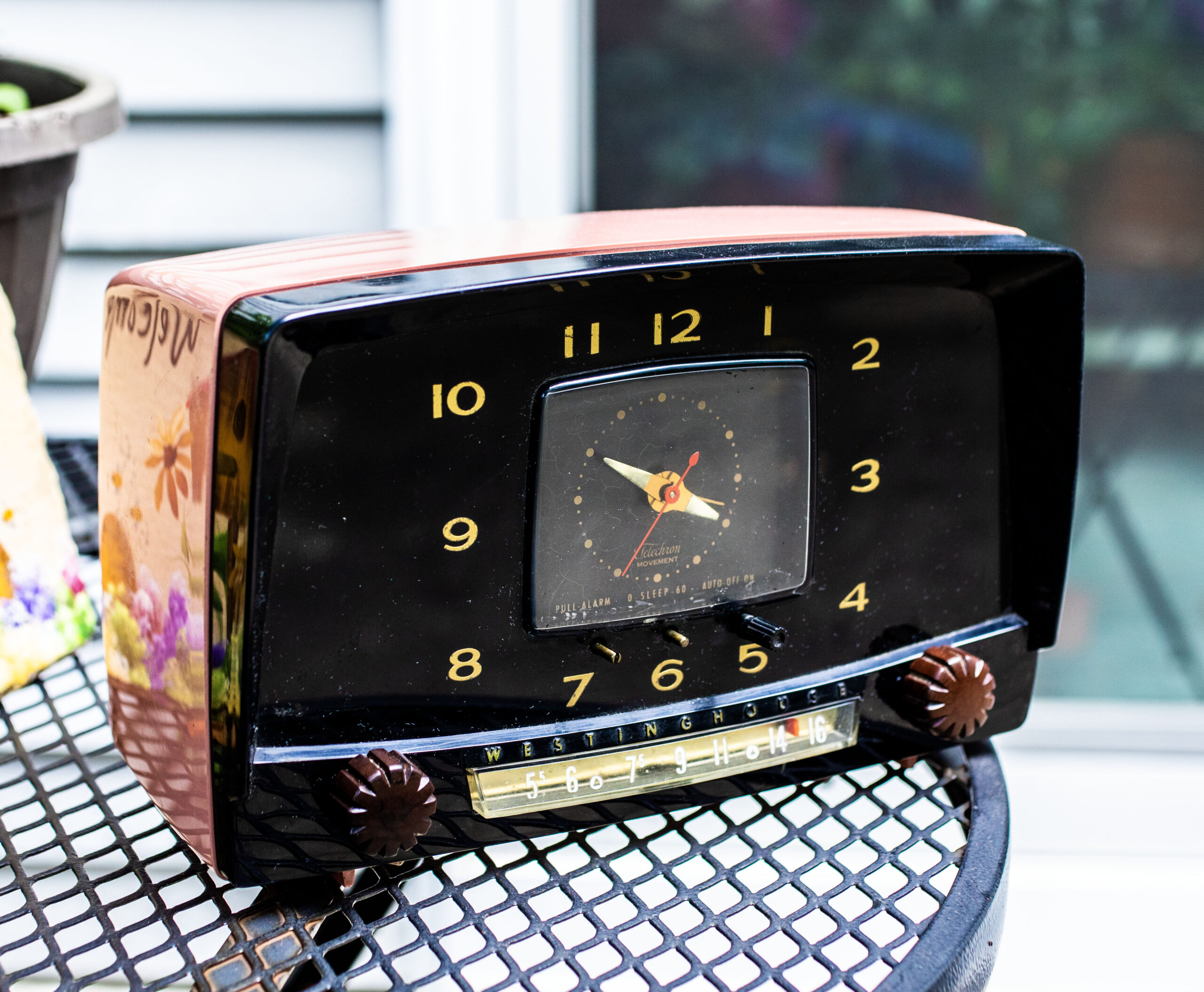
The completed radio has since found a spot in a friend’s home, where it pulls in local AM broadcasts without a trace of background hum.
Radio World welcomes letters to the editor on this or any story. Email [email protected].