Do you maintain an AM DA? When was the last time you spent some quality time at the transmitter site? To follow is a little quiz on site maintenance. See how well you do. Match the descriptions below with the photos.
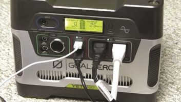
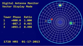
_____ Check DA sample parameters here, and make sure all pattern change lights are illuminated.
_____ Clear tape can be used to keep this lying flat
_____ These contacts should be tested for tightness. Remember, loose connections generate heat
_____ Tighten these and all other hardware — with the transmitter off, of course
_____ Arcs can occur here — a good place to inspect with a strong trouble lamp
_____ Use a Sharpie or similar permanent marker to mark these locations
_____ No one likes working in the dark. Spend the money for the extra illumination


* * *
So how did you do?
Fig. D goes with our first maintenance tip, to periodically check DA sample parameters on the antenna monitor and, while you are at it, make sure all pattern change lights illuminate properly. Troubleshooting can be time-consuming if warning and status lights aren’t doing their job.
Copper strap, used to ground transmitters, is great — when it lies flat, as shown in Fig. B. That’s the second tip. Clear packing tape can be used to keep this strap in place and avoid it being torn or ripped by foot traffic. Repair any rips or tears in the strap, or broken solder joints.
Fig. E shows J-plug jack contacts. These plug contacts should be tested periodically for tightness; remember, loose connections generate heat. The twice-a-day vibration of contactors changing can loosen the plugs. In cases where the J-plugs are mounted upside down, I’ve seen engineers loop a long wire tie through the plug and jack assembly to guard against the jack falling out. Remember, simple things like this make up most of the AM DA maintenance issues when a failure occurs.
Speaking of tightening things, Fig. A shows network hardware that should be periodically tightened, too. And of course with the transmitter off!
Isolation coils and isocouplers, as seen in Fig. G, can arc — especially after a thunderstorm, so inspect these devices with a strong trouble lamp for burn marks. In tight ATUs, coupling the trouble lamp with a mirror can help you inspect the back side of these.
Fig. C shows a coil clip position marked on either side with a Sharpie or similar brand permanent marker. This action only takes a few seconds per coil, and will save you hours of re-tuning if the clip falls off. It’s a good idea to include these coil clips in your tight connection routine
Transmitter sites are notoriously dark. A single light bulb just won’t cut it, so make the investment in some heavy-duty florescent fixtures, as shown in Fig. F. Mount some of them on the wall, behind the transmitter and phasor. No one likes working in the dark.
Thanks to Grady Moates, principal of Loud and Clean in Boston, for sharing one of his contract clients’ sites for these pictures. Grady’s got a great article on building an FM in Bermuda. Head to www.loudandclean.com for details.
John Bisset has worked as a chief engineer and contract engineer for 39 years. He is international sales manager for Europe and Southern Africa for Nautel. He is a past recipient of the SBE’s Educator of the Year Award. Reach him at[email protected]. Faxed submissions can be sent to (603) 472-4944.
Submissions for this column are encouraged and qualify for SBE recertification credit.