Figures
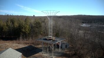
(click thumbnail)Fig. 1: Milton Silam adjusts the Top Spin Fractal Coefficient prior to making field-strength measurements with a sheet-copper prototype of the TSP antenna. A special receive antenna was attached to an FIM-71 for collecting data.
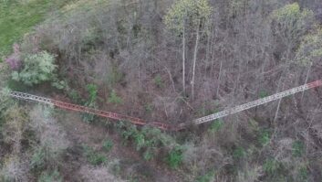
(click thumbnail)Top Spin Antenna Propagation TrajectoryJust up the road from Oakridge, Tenn. — a community with one of the highest concentrations of Ph.D.s in the world — is a small antenna shop in Appalachia that has recently produced a revolutionary antenna for broadcasting.
We have designed this new antenna using finite element analysis (FEA) methods to ingeniously translate the rotation of a circularly polarized signal in order to achieve Top Spin Polarization, or TSP. The Poynting vector that defines the direction of propagation of the quadrature electric and magnetic components of the electromagnetic wave in the far field has been transformed so that the rotation is more like the rolling waves of the ocean in an end-over-end fashion. This transformation is accomplished in the near-field reactive region using anisotropic dielectrics and is the basis of the TSP method.
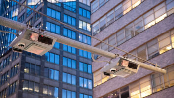
The inventors, Milton Silam and Dirac Newel, have produced test results showing the ability of this new polarization technique to transmit a signal that arches downward as the signal propagates away from the antenna. This antenna is the ultimate design for urban canyon settings where tall buildings otherwise cause extensive shadowing. The transmitted signal effectively can curve over the top of obstacles such as tall buildings in an urban environment. Other implementations are being investigated that may provide similar capability to curve around obstacles in a horizontal plane.
The common problem of cliff effect may also be eliminated with this antenna design.
“By applying TSP, we are able to curve the propagation path much like a pro baseball player can deliver a sinker,” said Newel. In fact, one version of the antenna that provides Extreme TSP (ETSP) has been dubbed “The Titanic,” though Newel is quick to point out that this moniker isn’t popular with the sales and marketing staff.
Cliff effect tests
Tests have been conducted in real-world settings — including a location with a steep drop-off near a bluff near their shop in Norris, Tenn. — that demonstrate the unique characteristics of the antenna. Actual signal levels recorded on the ground using a calibrated signal strength meter were taken for both a normal circularly polarized antenna as well as for the TSP antenna. These bluff tests show a marked increase in signal level in the area immediately below the bluff, which otherwise exhibits shadows when using the normal antenna.
While prior work with broadcast customers may be lacking, we do understand some of the pitfalls that might be encountered.
“You do have to watch the feeds on the quadrature elements of the antenna,” Silam said. “We reversed them in one test at our outdoor range and had trouble getting a good pattern reading. At the same time, we were getting a poor match on the input to the antenna. We realized that we were actually applying bottom spin (BS) polarization, and the signal was arching into the sky, curving around in a huge loop and illuminating the antenna from the back! The level of self-coupling should have been a big clue, but it was the first time we encountered the problem, so it left us scratching our heads for nearly a week.”
The amount of curvature resulting from the top spin polarization is easily varied either by adjusting the power ratio of the quadrature feeds or by varying the length and angle of the individual radiating elements. We use a technique known as the knife-edge test in an anechoic chamber to precisely measure the amount of top spin and to produce a map of effective radiation on ground as a function of elevation and distance by measuring direct and diffracted signal patterns beyond the knife edge. These results can be imported into some of the popular propagation modeling software tools for further characterization vs. terrain using Longley-Rice or other propagation models. Characterization of the antenna still includes the typical horizontal plane pattern, but the vertical plane pattern, which usually describes the relative field strength as a function of angle, is replaced by a vertical plane plot that is a function of both elevation and horizontal distance.
While we will need to perform some additional experimentation to empirically validate these models, we have found that the paths of the electromagnetic emissions from the TSP antenna appear to follow the equation:
(click thumbnail)
where theta is the elevation angle from horizontal (zero) to straight up (pi/2), F is the field strength as a function of theta and TSF_Coef is the Top Spin Fractal Coefficient.
We have also found that we can vary the Top Spin Fractal Coefficient as a function of theta. It is interesting to note that when the Top Spin Fractal Coefficient is equal to zero, the electromagnetic radiation behaves in the classical straight-line propagation. By setting the TSF coefficient to zero (or nearly zero) at low angles of inclination, we can ensure good coverage at an unobscured horizon. Likewise, by increasing the TSF Coefficient for higher angles of inclination, we can “bend” the Poynting vector over obstacles located near the antenna.
Fig. 2 shows a typical trajectory profile that can be designed by simple adjustments to vary the Top Spin Fractal Coefficient. Note how the increasing TSF coefficient tends to “pull” the high-angle emissions back to the ground. While this does not represent field strength on the ground, the field strength can be calculated from the value of F(theta) and from the total length of the propagation path. The trajectory profile combined with the radiation level vs. angle produce the resulting radiation level on the ground. There are several degrees of freedom in this antenna that we should be able to exploit to great benefit.
We have contacted two large broadcasting groups that have stated an interest in the new design, but it has been slow going to establish credibility due to the small size of the company and the lack of experience in the broadcast market. The business is located about four miles out of Norris, on Laerton Lane, a small gravel road taking its name from near where we grew up together in the United Kingdom. A field test for industry observers is planned on April 1, and an exhibit is also planned at NAB2007 in Las Vegas. The Web site address is http://www.topspinantenna.com.
RW welcomes first-person accounts from engineers with experience of TSP.