As broadcast engineers, we are sometimes tasked to come up with innovative solutions. This story is an example of using amateur radio “ham” technology in commercial AM radio broadcasting.
A friend called to say his money-making, 500-watt nondirectional AM station on 1390 kHz might have to run into a wire antenna for a few days. Yes, small-town radio can still make money, and my friend didn’t want to lose any during a possible interruption.
Years ago, we would say that an AM tube transmitter could operate into not much more than a “coat hanger” for an antenna. Hams have been using wire antennas since the beginning and have found ways to make them work.
The difficulty is that today’s solid-state transmitters are very particular and require 50-ohm antennas. Many hams now use solid-state transmitters, which have the same requirement.
Antenna theory
Fellow Radio World contributor Buc Fitch wrote in a recent article, “Radio is magnetism through space.”
To that end, we know that it takes two elements to make an antenna work. The radiating element for an AM is a tower. The other half is a 120-radial ground system. RF circulates between the two and radiates to the world in the process.
FM antennas have two arms, so to speak. One arm has RF and the other is the ground.
The difference here is that 88 to 108 MHz FM is about 100 times higher in frequency than the middle of the AM broadcast band. Thus, a 1000 kHz wavelength is about 100 times longer. As you know, one-wavelength-spaced FM antenna bays are about 10 feet apart. One wavelength at 1000 kHz is 984 feet.
In the case of my friend’s 1390 kHz station, a temporary AM antenna could be a single 175-foot wire, starting at the center of his existing AM ground system and fed by a coaxial cable with the cable shield connected to the ground. See Fig. 1.
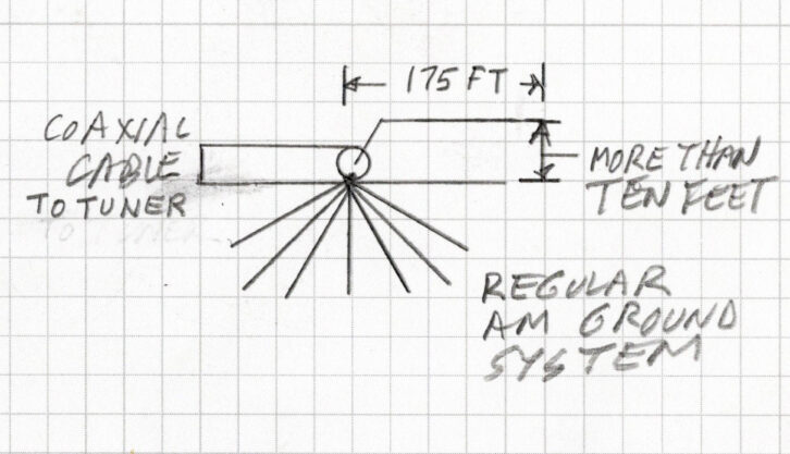
Another choice is a wire dipole 10 or more feet above the ground. See Fig. 2. More height is better for efficiency! For 1390 kHz, a dipole should be about 350 feet in length, fed in the center with a coaxial cable. At 1700 kHz it would be roughly 285 feet. At 540 kHz it is about 890 feet. Remember, we are talking long wavelengths! Almost any wire size will work from AWG 10 through 20. Doesn’t matter if it is insulated or not.
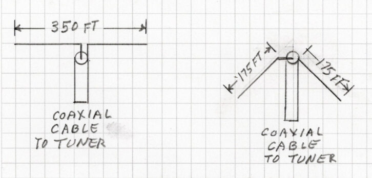
RF goes to one wire and the cable shield to the opposite side of these two wires, hence the name dipole. The RF travels between the two sides while radiating into the air.
Broadcast engineering consultant and friend Mark Mueller said he used this scheme successfully, but with a bit of a twist. The feed point where a coaxial cable connected to the center was almost 100 feet off the ground with the ends closer to the ground in what hams call an inverted-V. Dipoles have their own ground side, so they do not need a traditional buried ground system. None of these schemes guarantees a 50-ohm feed point. The goal is to get close so a simple matching network will bring it to 50 ohms.
Alternatives
To be fair, there are other choices for AM broadcast antennas. They include, but are not limited to, antennas from Valcom, Isotron and Information Station Specialists.
There is also the hand-built antenna described in my RW article in 2021 titled “Quick, We Need a Temporary AM Antenna.”
Today’s article is about a simple temporary antenna that takes only hours to build for just a few days’ use.
Making it work
I had an extra MFJ-962 Versa Tuner III, which is used by hams for matching transmitters to antennas (Fig. 3).
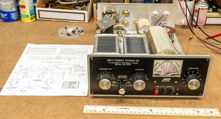
The unit weighs less than 8 pounds and was priced in the $300 range. This one is no longer manufactured, but there are many similar new and used units on the market.
We use the term antenna coupling network in AM broadcasting, but units like this are known in the ham radio community as antenna tuners.
Typical of most designs, this tuner is a T-network with an air-variable input capacitor, a multi-tapped coil to ground, then another air-variable capacitor on the antenna end (Fig. 4).
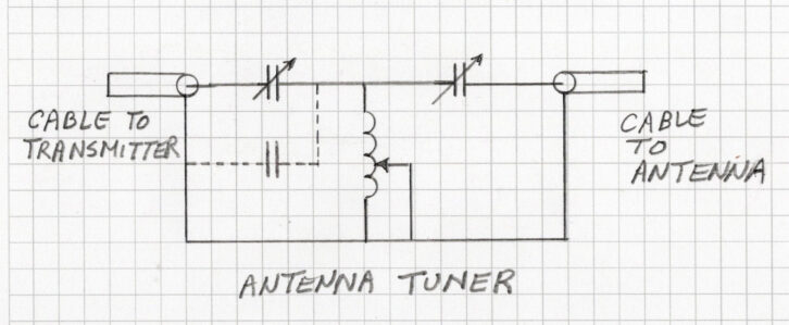
Variable capacitors and adjustable inductors are required because hams operate on many bands of frequencies. One benefit of this unit is it contains a VSWR meter, which is a nice feature when tuning.
Published specifications say this tuner will work over a 1.8 to 30 MHz range. That doesn’t mean it can’t tune the AM broadcast band. My spare parts inventory had a two-inch diameter coil of #18 wire that is 3 inches long. I added it to the existing coil to help it reach down in frequency.
Those who have been around a while are familiar with ICAS, which is Intermittent Commercial and Amateur Service, while CCS means Continuous Commercial Service. Amateur radio tuners are ICAS and not built like the heavy-duty designs that we use in commercial service.
This particular tuner is rated at 1.5-kilowatt peak power. For perspective, a 500-watt AM transmitter modulated to 100% has 2,000 watts peak power. Worse yet, it is 2,530 watts peak when the positive modulation reaches the FCC allowed 125%. In this case, running the station at no more than 250 watts carrier with 1,265 watts peak power is a wise choice.
Testing
The unknown was what the antenna impedance would be on a temporary non-traditional wire antenna. Bench testing was in order (Fig. 5).
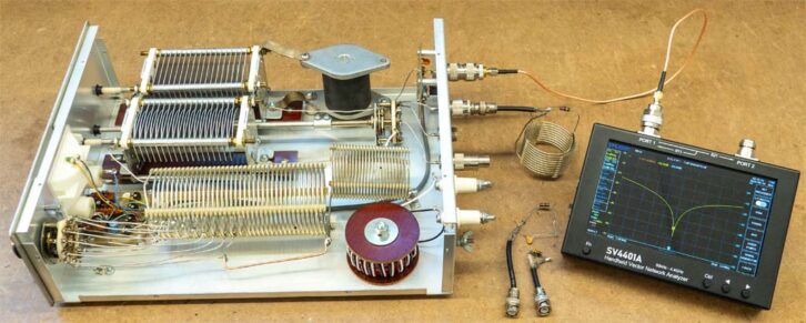
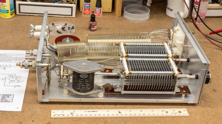
I connected a $300 Sysjoint SV4401A Vector Network Analyzer to the transmitter side of the tuner, which was looking into a 50-ohm resistive load on the antenna side. This is when I added a .00015 mfd/6 KV/2.4-ampere Type 291 fixed capacitor across the variable capacitor that is on the transmitter end of the network.
It is standing up from the chassis by two preclean insulators. You see it with dashed lines in Fig. 4 and as a black cylinder with aluminum plates on top and bottom in Fig. 6. The modification gave the tuning capacitors and switched inductor plenty of range to pass 50 ohms to the transmitter.
Then I put a 100-ohm resistor in series with a .0005 mfd capacitor, which was the same as an antenna that is 100 ohms resistive with about 200-ohm capacitive reactance at 1390 kHz. The tuner was able to translate this simulated antenna, back to 50 ohms for a transmitter to see. Then I put a 27-ohm resistor in series with a 10 uHy inductor, which is the same as an antenna that is 27 ohms with 100 ohms inductive reactance. Again, the tuner was able to perform the impedance transformation to 50 ohms. I tried other odd impedances and became assured there was enough range in the tuner to accommodate a fairly wide range of impedances.
In the end, the temporary antenna was not needed. However, it was a great exercise in engineering thinking and bench testing.