![]() The FCC-required proof-of-performance was an annual ritual for broadcast engineers from the earliest days of radio up to deregulation in the 1980s.
The FCC-required proof-of-performance was an annual ritual for broadcast engineers from the earliest days of radio up to deregulation in the 1980s.
In the early 1970s, many engineers might have fantasized about making those measurements with high-end gear such as an HP 204 audio oscillator, 403 AC voltmeter, 330 distortion analyzer, a Hallicrafters communications receiver and a Tektronix oscilloscope.
The oscillator, voltmeter, distortion analyzer and communications receiver were required items for the annual FCC Proof of Performance measurements. An oscilloscope was useful, but not essential. The reality in the workshops of most small- and medium-market stations was usually a bit different than what the engineer might have wished for.
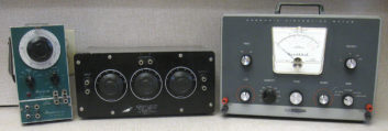
Pictured is an ensemble that might be more likely in a small- to medium-market operation in 1970. For the audio proof, a Waveforms 510-B audio oscillator, Daven Type VT-795-6 attenuation network and Heath IM-12 distortion meter. The RF portion of an AM proof might be accomplished with a Heath GR-54 communications receiver.
The audio oscillator and precision 600-ohm attenuator were often two separate units. As with many high-end oscillators, the Waveforms 510-B had a 0-10 volt variable output control and a 600-ohm balanced transformer output. The Daven VT-795 600-ohm decade attenuator provided precision attenuation in 10, 1 and 0.1 dB increments. The AC voltmeter and distortion meter functions for this 1970 package were provided by a Heath IM-12. Although of simple design and modest cost, the IM-12 could measure distortion down to 0.1%. The GR-54 was a six-tube, single conversion communications receiver covering 180 kHz to 30 mHz. It was Heathkit’s mid-line shortwave receiver at the time.
TUNING UP THE CHAIN
In the days of analog vacuum tube broadcast gear, this test equipment was used heavily. Most stations took advantage of the FCC’s designated experimental period from midnight to 6 a.m. Monday to tune up the entire broadcast chain. A lot of things could have gone wrong in the preceding seven days.
The emission of tubes could fall past the critical point, or they could become microphonic. Wax coupling and bypass caps could overheat and short out, often taking plate load resistors and other components along with them. Carbon composition resistors, particularly in grid circuits, could become noisy, generating lots of white noise. Electrolytic caps in power supplies or decoupling circuits would eventually dry out and lead to increased ripple or motorboating. And of course, any of the hundreds of contacts in tube sockets, audio and RF connectors could become noisy or intermittent.
Between this ongoing maintenance and troubleshooting, a lot of test equipment was checked only once a year, usually right before the proof was conducted.
The good thing was that all measurements required by the FCC were relative, and not absolute. For example, frequency response in measured in decibels, and is really the relationship between two voltages, so the absolute value is irrelevant. It’s the same idea with distortion. Harmonic distortion is a percentage of the original signal voltage. That being said, good engineering practice suggests that test equipment be kept as accurately calibrated as possible.
The first step in getting test equipment ready for the proof was checking the response of the oscillator into the AC voltmeter. For an AM proof, that meant checking the response from 50 to 7500 Hz, referenced to 1 kHz. FM proofs required a flat 50 to 15,000 Hz response referenced to 400 Hz. Any deviations greater than 0.2 dB needed to be noted on a calibration chart, and these deviations were subtracted from the transmitter response deviations before logging them on the proof forms.
The next step was measuring the distortion level of the test equipment. The audio oscillator is connected directly to the distortion meter. The total noise, hum and distortion of the combo is measured, and for FM proofs, it needs to be 0.25% or less, for AM, 0.5% or less. For test equipment of the day, a figure of around 0.1% was average, as long as you were careful to avoid ground loops. With response and distortion checks complete, the model and serial numbers of the equipment could be recorded on the proof sheet, and the actual work could begin.
The commission’s requirements for checking harmonics and spurious radiation of an AM transmitter were about as open-ended as the audio portion was prescribed. All that was stated was that the engineer needed to measure the transmitter’s spurious and harmonic radiation, and that such emissions be suppressed sufficiently to avoid objectionable interference to other radio services.
Taking these measurements at the transmitter site was ill-advised due to the possibility of receiver overload. They were usually done at the studio with the communications receiver connected to an outdoor antenna. The receiver was tuned slowly across each band, checking at each harmonic of the station’s carrier frequency. Checks were made of the first 10 harmonics, although the second and third were usually the most problematic. Issues with excessive harmonics were usually the result of capacitors in the harmonic traps that had gone open due to lightning strikes, or loose or corroded hardware and/or connectors.
WORKHORSE GEAR
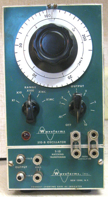
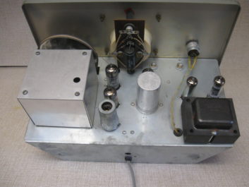
The Waveforms 510B audio oscillator was a real workhorse. It was a textbook resistance-capacitance tuned oscillator built very compactly, and with precision components. Tube lineup consisted of a 6X5 rectifier, 6SJ7 oscillator, 6AK6 cathode follower and 6AK6 output.
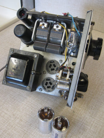
Although sighted more frequently in manufacturing facilities, physics department labs and R&D environments, the 510 occasionally surfaced on radio station test benches. Specifications called for a range of 18 Hz to 1.1 mHz , a response of +/- 1 dB from 18 Hz to 200 kHz and distortion less than 0.2%. Noise was 60 dB below signal. These were the guaranteed specs, but the performance of some units was much better. Pictured with this 510-B is the T10 matching transformer, mounted on the bottom of the oscillator. It provided a balanced 150/600-ohm output and a response of 20 Hz to 50 kHz. The 510B’s specs were comparable to the HP audio oscillators of the day, but the 510 was much smaller, measuring just 4 inches wide by 6 high and 6 deep.
The Daven VT-795 was simplicity itself, consisting of 10-, 1-, and 0.1- dB/step attenuators, wired up in series. Double banana jacks were provided for input and output. There were no other components, and no maintenance was required.
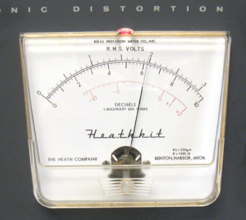
The IM-12 harmonic distortion meter was to be found on many workbenches. The theory behind these meters is rather simple. To determine how much distortion has been added by an amplifier, simply subtract the input signal from the output signal. What is left over was generated by the amplifier, mostly harmonic distortion, usually with a bit of hum and noise thrown in. A Wein bridge, with a negative feedback network across the bridge circuit is used to null out the fundamental frequency.
Regular maintenance for the IM-12 consisted of checking its six tubes, going over switch contacts and adjusting the tweaks for voltmeter calibration, coarse balance and hum balance.
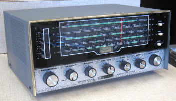
The Heath GR-54 was in production in kit form from 1966-71, with the price increasing from $85.00 to $135. If assembled carefully, it would perform well, although sometimes it was not without “issues.”
The GR-54 had all major components on three circuit boards: IF-audio, RF-oscillator-mixer and band switch. All of these boards relied on a solid mechanical connection to the chassis for grounding. This was never a good idea. If the kit builder didn’t adequately tighten the mounting hardware, or left the lock washers off, erratic and unusual problems could result. The same thing occurs to most GR-54s after being stored for a few decades in a damp basement, as corrosion takes its toll.
Circuit updates for the GR-54 are readily available online. Full restoration can be a tedious but not complicated process. The result is a solid, well-performing receiver.
The 510-B and the Daven attenuator shown with this article came from a college surplus grab in the early 1970s. They saw regular use in contract engineering duties through the mid-’80s. The IM-12 was a gift from a fellow contract engineer, who was relocating, and didn’t have room to pack it. The GR-54 was acquired about 20 years ago from a non-technical friend who purchased it at a yard sale. It didn’t work well, and got handed off to me. After downloading a manual and rounding up the usual suspects, it was returned to good operating condition.
Tom Vernon is a longtime contributor to Radio World. He wrote last September about the history of remote control systems; read it at https://tinyurl.com/rw-remcon.
Comment on this or any story. Email [email protected] with “Letter to the Editor” in the subject field.