At the time of original publication, the author was senior scientist at Continental Electronics. He retired in 2017. The text below is as originally published in 2010 and is provided here as an archival reference only.
Part 1 of this article, featured in Radio World Engineering Extra, introduced some of the potential problems for the analog FM signal when considering elevated HD power. We discussed the increased peak envelope power requirements for elevated HD power and the concurrent higher envelope modulation component. Receivers are particularly sensitive to negative envelope modulation because the FM receiver’s limiting function must increase its gain. The receiver gain is proportional to the reciprocal of the received envelope. If the received envelope pinches off, then the receiver will output noise bursts.
Part 1 also discussed the phase modulation mechanisms for self-noise and the mitigating effects of narrow IF filters in receivers. Time domain simulation results were presented for different levels of HD power with wide and narrow bandwidth FM receivers. Self-noise was shown to depend on analog deviation, increasing as the analog carrier deviates toward one of the HD sideband blocks.
Now we can look at the frequency domain. For the simulations shown in Fig. 18 there is no analog modulation, just an unmodulated FM carrier, with 1 percent, 4 percent and 10 percent digital power. The graph stops at 125 kHz, so we do not see any of the first order intermodulation. We only see the higher-order terms, which are the complex beats between multiple IBOC carriers, the IBOC symbol rate and the FM analog carrier.
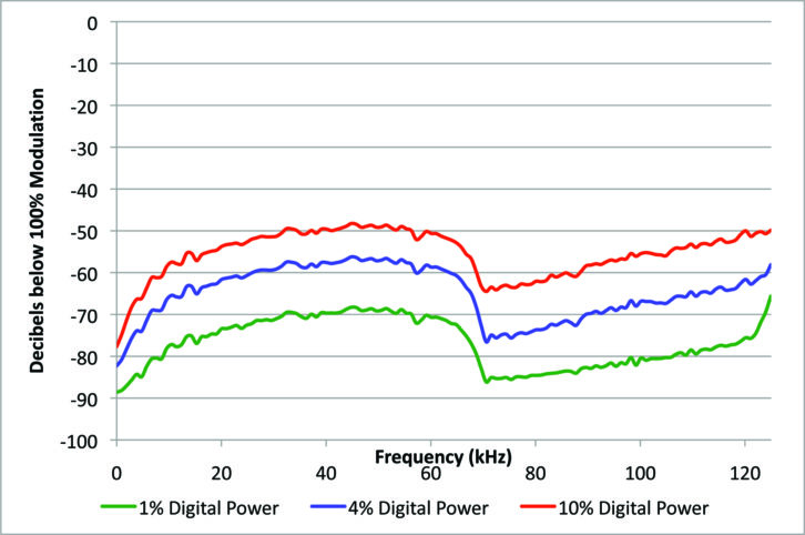
What is interesting here is that there is a block of noise at low frequencies, reaching highest energy between about 20 and 60 kHz. This will affect stereo reception, RDS and SCA. Another interesting effect is that as the digital power increases by 10 dB, the noise floor increases by 20 dB. This is evidence of a higher-order non-linearity producing the lower-frequency demodulated FM noise.
The good news is that the monophonic part of the composite spectrum, up to 15 kHz, has the least amount of noise. That is your mono signal. Monophonic FM is quite robust.
Fig. 19 adds sharp filtering of the hybrid signal. That block of low-frequency noise centered around 35 kHz has dropped about 15 dB, and the digital power dropped 6.7 dB because of the filter.
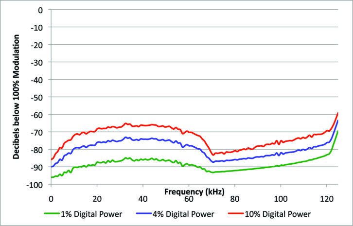
The next spectral plots look at dynamic conditions — with analog deviation.
In Fig. 20 below we have added a 1.9 kHz tone at 75 kHz deviation to the analog signal. With no digital signal present, the demodulated signal is perfect. But with digital power present, we can now see more effects of self-noise, with the first-order beats extending down to about 54 kHz. So self-noise increases in the presence of FM deviation.

Fig. 21 shows what happens with our monophonic signal when we add sharp filtering. First, notice the lowest trace, which shows the signal with no digital power. That spectrum is no longer perfect. The distortion is coming from the bandpass filtering of the FM signal. Otherwise, there is a reduction of the noise level because of the receiver’s filtering.
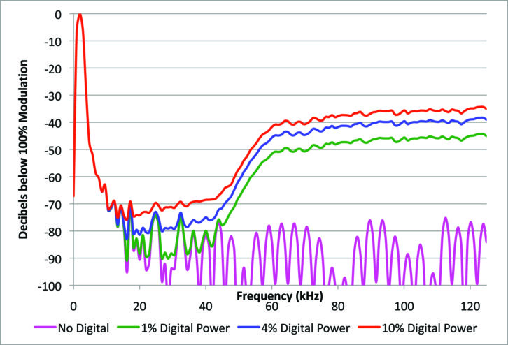
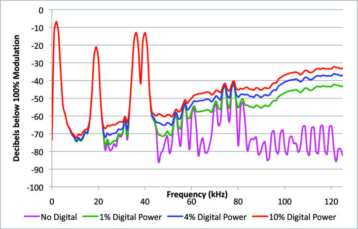
Fig. 22 shows analog FM at 100 percent modulation using a stereo left-channel tone at 1.9 kHz. As before, with no digital the demodulated signal is basically perfect. At high frequencies, above about 60 kHz, a 10 dB increase in digital power results in a 10 dB increase in noise. But down in the stereo composite area below 50 kHz, a 10 dB digital power increase results in an increase in noise of almost 20 dB.
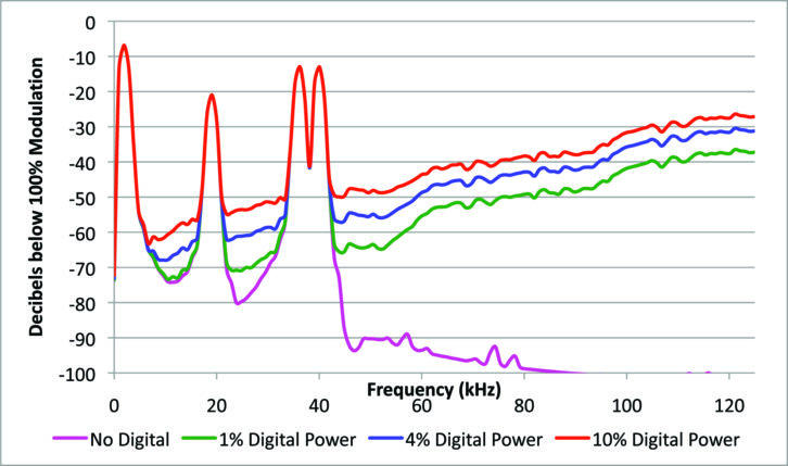
Fig. 23 shows what happens with single-channel stereo modulation with the sharp filter. At 1 percent digital power, the digital noise in the stereo composite region is largely masked by the filtering distortion. But at 10 percent digital power, the self-noise clearly dominates the filter-induced distortion.
[Sign Up for Radio World’s SmartBrief Newsletter]
HARDWARE-BASED “SANITY CHECK”
After doing these simulations, we wanted to verify them with hardware as a sanity check. So we got out an old but still very good Sansui tuner with a dual bandwidth IF.
Fig. 24 shows what the tuner’s composite output looks like with no HD and 100 percent monophonic modulation. It is simply a clean 400 Hz tone.
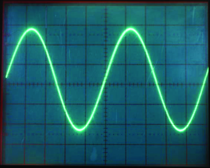
In Fig. 25 we have turned on HD at 4 percent digital power, with the tuner set to its narrow bandwidth. The waveform has picked up a little bit of fuzz, and it looks very much like the 4 percent time domain simulations shown earlier.
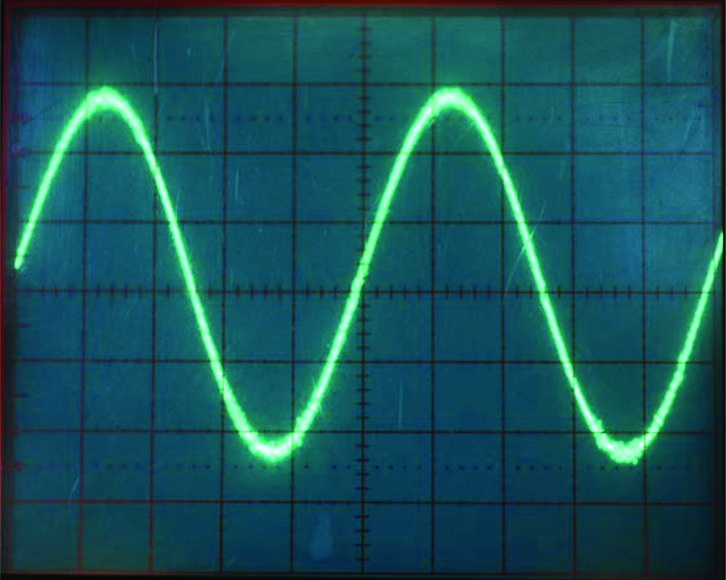
With HD still at 4 percent digital power, in Fig. 26 the tuner is set to its wide bandwidth. The waveform has picked up substantially more fuzz, in agreement with the simulations.
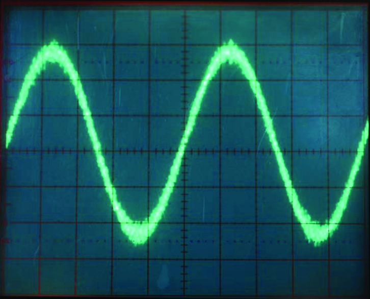
Fig. 27 shows the Sansui tuner composite output at 10 percent HD with the wide IF. The fuzz is larger near the peaks, as predicted.
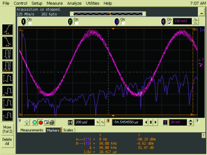
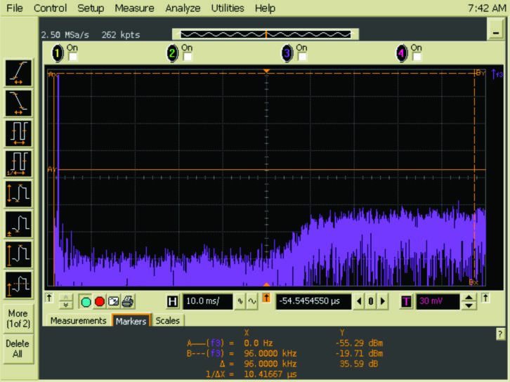
Fig. 28 shows a spectrum analysis of the noise, showing a rise near 54 kHz, also in agreement with the simulations.
INTERPRETATIONS AND CONCLUSIONS
The hardware tests show general agreement with the simulations. So what are these simulation results and lab tests telling us?
One of the surprises is that the simple frequency difference terms are not the only significant analog noise components. There are higher-order distortion mechanisms causing noise at lower frequencies in the demodulated analog composite output.
Second, the high-order noise increases twice as fast in dB with increasing digital power. A 10 dB increase in digital power increases the lower-frequency analog noise by 20 dB. Fortunately, the lower-frequency noise is lower in amplitude than the first-order beats.
Sharp filtering in receivers reduces but does not eliminate self-noise. We have no control over receiver filtering, so IF bandwidth variation will affect self-noise.
And finally, the FM monophonic part of the spectrum is largely unaffected. FM mono is robust. This is due to the higher modulation index at the lower frequencies, which is another way of describing the triangular noise spectrum of FM — noise increases with modulating frequency.

The 75 microsecond de-emphasis curve helps reduce the noise in mono and stereo. Table 2 shows calculated composite SNR values with the 53 kHz brick-wall filter for different combinations of digital power and filter bandwidth. Values range from about 37 to 54 dB.
Composite SNR is not a familiar value. So we will relate composite SNR to the more familiar monophonic SNR and stereo SNR measurements. First we have to make some assumptions. Usually we assume that the channel noise is white, which produces a rising noise spectrum after detection. This is not exactly the case with IBOC, but it is a good place to start to get some ballpark SNR values.
Given composite SNR in a 53 kHz bandwidth, and assuming white noise (6 dB/octave increase when de-modulated to FM):
Add 29.6 dB to get mono SNR (75 microsecond de-emphasis)
Then subtract 23.0 dB from mono SNR to get stereo SNR

With this assumption, we can take the composite SNR value and add 29.6 dB to it to get the 15 kHz mono SNR with 75 microsecond de-emphasis. Once we have the mono SNR, we can then subtract the familiar 23 dB penalty for FM stereo to get the stereo SNR. Table 3 shows the results.
Mono SNR varies from about 84 to 67 dB, which is great. Mono is robust. Stereo varies from about 61 to 43 dB, so there may be some audible noise. Experimental results confirm that stereo noise goes down with reduced analog modulation.
Our predicted dynamic stereo SNR was 43.5 dB for a wideband receiver. Lab tests with the Sansui tuner produced 41 dB. The conventionally measured stereo SNR, with an unmodulated carrier except for the pilot, was 46.5 dB.
CREST FACTOR REDUCTION AND RECEIVERS
A related topic that affects analog self-noise is peak-to-average ratio (PAR) or crest factor reduction. It is not just for positive peak control anymore. There are three situations where crest factor reduction provides a benefit.
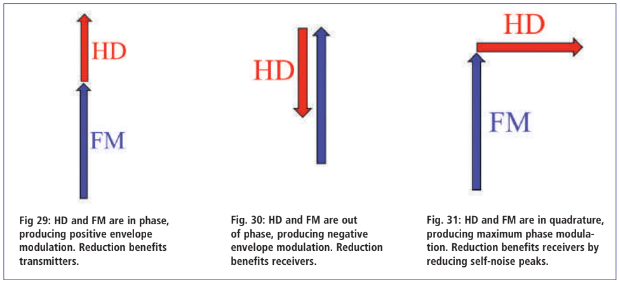
First, when the FM and HD vectors are in phase as shown in Fig. 29, this produces a positive envelope modulation peak. We want to control these peaks so that the transmitter does not have to produce extreme PEP. Controlling these peaks benefits the transmitter. But there are two more situations where there is a benefit from crest factor reduction.
Second, when the FM and HD vectors are out of phase, this produces a negative envelope modulation peak. We want to control these peaks so that the RF envelope does not approach pinchoff where the receiver’s limiter gain must increase. Controlling negative envelope modulation peaks benefits receivers by avoiding noise bursts.
That leaves quadrature. When the FM and HD vectors are orthogonal, this is the point where we produce the peak phase modulation self-noise. We also want to control these peaks, to avoid making impulsive self-noise.
Clearly, there are significant benefits to reducing the peaks of the digital signal regardless of what the analog FM carrier is doing.
IBiquity’s crest factor reduction controls the digital signal peaks for all phase relationships with the analog FM signal. We believe this is a good thing. If we must transmit somewhat higher positive envelope peaks to reduce negative AM, this is a good tradeoff because it improves analog reception. When evaluating a crest factor reduction system, it is important to consider the entire signal path including the receiver — not just the transmitter. So our conclusion is that iBiquity’s peak control system provides the maximum advantage to the entire system, including the analog receivers.
DECISIONS AND RECOMMENDATIONS
Broadcasters must make the decision about what digital power level to use. Every situation is different. To state the obvious, you want to turn it up enough, but not too much. And hopefully those ranges of “not enough” and “too much” do not overlap.
“Enough” means having a digital signal power that gives you the digital coverage you want. “Too much” means adversely affecting your analog signal.
What is “too much” depends on your format, your terrain, your listeners and other factors.
If your format is classical music, or anything with a wide dynamic range that may include speech, self-noise may be audible, especially on receivers with wider IF bandwidths.
On the other hand, if you run aggressive audio processing, then self-noise may be completely masked by the consistently high analog modulation. When listening in a car, road noise is probably going to dominate any self-noise. And receiver blending will help.
Multipath problems may be aggravated by running a lot of digital power, because of differential fading between analog and digital components, causing envelope pinchoff at the receiver’s detector. So your terrain and propagation paths may be a factor.
Although theoretical analysis, simulation and objective lab testing are useful for understanding and quantifying the problem, the ultimate decision criterion will be subjective. Broadcasters should listen to what their on-air signals will sound like before deciding on a power level for elevated HD. This can be done by using just the exciter. With all of your program material types (speech, music, etc.) and with your normal audio processing, try different HD power levels with a variety of receivers. Set the HD power level to a point where you are comfortable with the analog reception. Listen for noise, distortion and stereo blending. Listen carefully on several receivers and then decide before deploying elevated HD power.
Mono reception is robust and mostly unaffected. For mono broadcasters, self noise will be much less of a problem.
Here are a few suggestions.
First, common amplification benefits extend to 4 percent and 10 percent power. It is possible to meet the mask at 10 percent digital power with no high-power mask filtering. Common amplification is simple. Efficiency is reasonable because signal statistics are somewhat better than DTV, meaning lower peak-to-average ratios, even at 10 percent digital power.
Tube technology is still quite economical for producing the increased PEP required for elevated HD. There is the possibility of water cooling if limited space or air conditioning presents a problem.
Although the average power will not be much greater than the analog signal alone, the PEP capability of coax, combiners, filters and the antenna should be checked to make sure that there will not be a PEP problem.
Do not overmodulate the analog! That pushes the instantaneous FM carrier closer to the IBOC sidebands, which produces more noise below 53 kHz. Finally, crest factor reduction systems should reduce positive envelope peaks for the transmitter, and negative envelope peaks for the benefit of the receiver. Do not pinch off the FM envelope!
CONCLUSION
Good engineering is about making optimum tradeoffs. The tradeoff here is digital coverage vs. analog signal quality. Most of your audience listens to the analog signal. Keep it clean enough.
Every station situation is different, so you will have to evaluate each station for the best digital power level.
Good engineering requires good information — and we hope that this information helps you.
Contact the author at [email protected].


